Pumping system for use on a moveable flood control barrier

a flood control barrier and pumping system technology, which is applied in the direction of vessel auxiliary drives, vessel parts, vessel construction, etc., can solve the problems of power consumption, complex systems, and multiple skilled operators, and achieves convenient operation, improved design, and improved safety.

Active Publication Date: 2014-06-03
CONWAY DALE A
View PDF22 Cites 2 Cited by
  • Summary
  • Abstract
  • Description
  • Claims
  • Application Information

AI Technical Summary

Benefits of technology

[0012]The operating systems onboard earlier versions of proposed floating barge floodgates to sink, float and rotate the barge into position required multiple power sources which utilized much needed space on the top level of the barge. One advantage of the present invention is to utilize a single engine which saves space. It is important to keep the engines, pumps, air intakes and the like safe above the water line. These systems can be quite complex and require multiple skilled operators to run and maintain them. This can be an issue considering that many of the cities and parishes use volunteers to operate these floodgates. Making such barges with less vital equipment to operate would also be helpful not just in flood prone areas of the United States, but in other second and third world countries. Again, for simplicity, the movable flood control barrier will be referred to as the barge.
[0013]Power is also a major problem at these remote sites where the barge is stored. Electrical power is typically not available in these remote areas and in special cases where electrical power is provided, it may not be available during storm events when it would be needed most.
[0014]The barge needs to be operational rapidly once a decision is made to deploy the barge or series of barges into a water blocking position in response to a predicted flooding event. Weather prediction systems, such as weather balloons, buoys with sensors, computer weather modeling, NOAA satellites, specialized hurricane hunter aircraft and the like are generally able to give accurate weather reports, such as where a storm may hit land and when this event will occur only so far in advance.
[0015]Therefore, civil authorities will only have so much advance warning in which to give authorization to deploy the barge. This makes the rapid deployment of the barge an important consideration.
[0016]In addition, problems with current pumping systems for floating barge floodgates is the requirement for the pump to be able to fill and dewater (empty) the barge. This requires the pump to operate under multiple conditions with varying suction and discharge heads (pressures) which can lead to problems with operating outside the recommended efficiency range of the pump at times or worse with inadequate net positive suction head causing cavitation which can severely damage the pump.
[0017]There is thus a need for a faster, simpler, better designed, more efficient and reliable system for operating a floating type barge floodgate.

Problems solved by technology

These systems can be quite complex and require multiple skilled operators to run and maintain them.
This can be an issue considering that many of the cities and parishes use volunteers to operate these floodgates.
Power is also a major problem at these remote sites where the barge is stored.
Electrical power is typically not available in these remote areas and in special cases where electrical power is provided, it may not be available during storm events when it would be needed most.
Therefore, civil authorities will only have so much advance warning in which to give authorization to deploy the barge.

Method used


Image

  • Pumping system for use on a moveable flood control barrier
  • Pumping system for use on a moveable flood control barrier
  • Pumping system for use on a moveable flood control barrier

Examples


Embodiment Construction

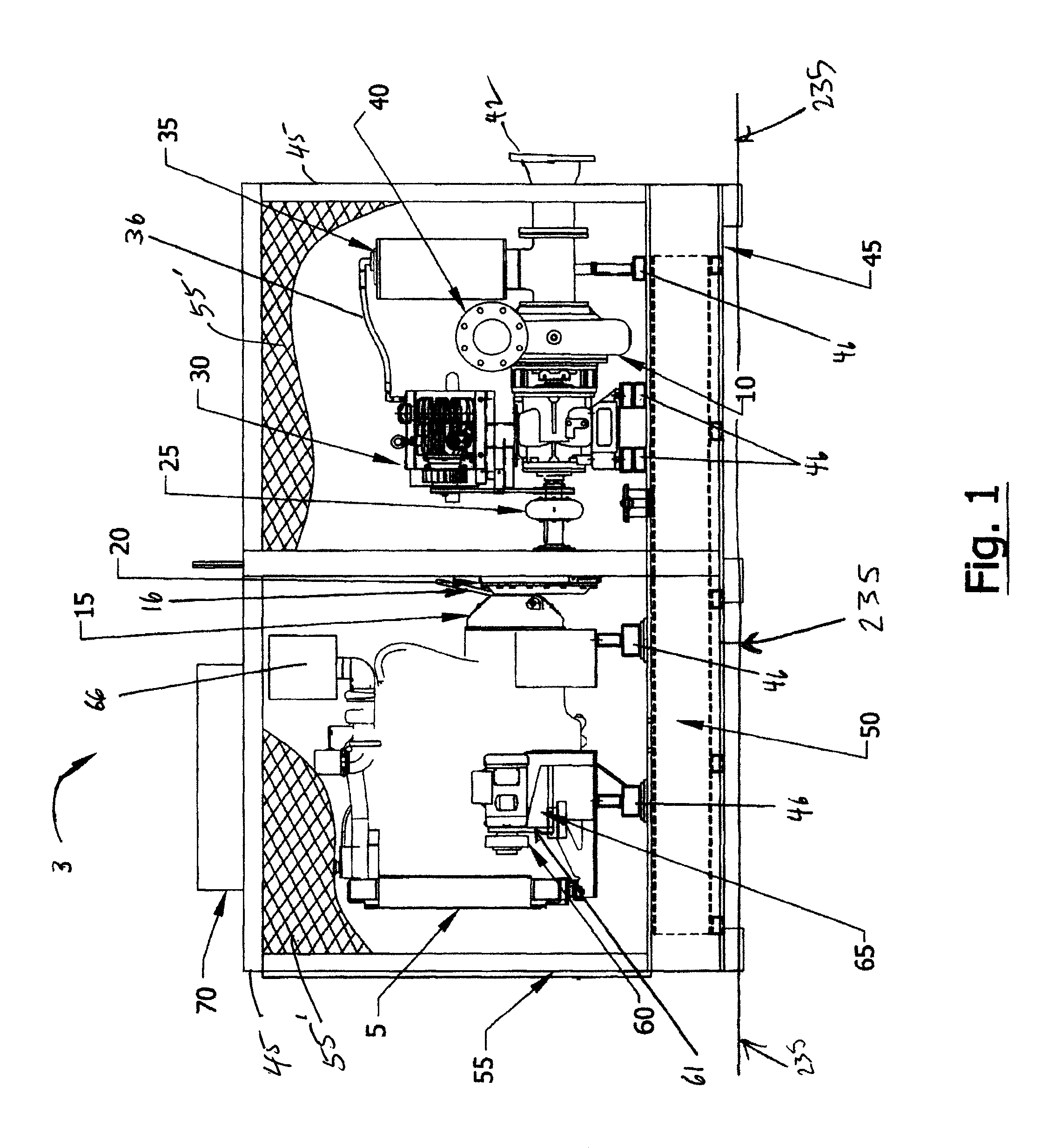
[0032]Referring to FIG. 1, the pumping system 3 employing a single diesel engine 5 to power both the hydraulic pump 65 and the centrifugal pump 10 of the present invention is shown. Diesel engine 5 has an air intake 66. Pumping system 3 includes a diesel engine 5, centrifugal pump 10 connected together with a speed reducer 20, power take off mechanical clutch 15 with handle 16 and drive coupling 25. Both the speed reducer 20 and the PTO mechanical clutch 15 are well known in the art and are chosen to meet the engineering requirements of the system. The speed reducer 20 allows the centrifugal pump 10 to be operated at the proper speed to meet the performance characteristics while optimizing net positive suction head for the centrifugal pump 10. The power take off mechanical clutch 15 allows the centrifugal pump 10 to be operated or turned off while the diesel engine 5 is still running. A vacuum pump 30, air-water separation chamber 35 and discharge check valve 40 provide automatic pr...


PUM


Abstract

A dual pumping system for use on a movable flood control barrier structure to allow the structure to be swung into the opening of a waterway and sunk to prevent flooding during storms and then floated and swung out of the waterway after the storm is disclosed. A buoyant generally rectangular barge may be employed as the movable flood control barrier. A centrifugal pumping system pumps water into compartments within the barrier structure so it sinks to the bottom of the waterway while the same pumping system pumps water back to the waterway to float the structure. A hydraulic pumping system operates hydraulic winches to move the structure into and out of the channel using cables. The two pumping systems are capable of operating both the water pumping system and hydraulic winch system simultaneously or independently with a single engine.

Description

PRIORITY TO RELATED APPLICATION[0001]This application claims the priority of U.S. Provisional Patent Application Ser. No. 61 / 530,065 filed Sep. 1, 2011, which is incorporated herein in its entirety.FIELD OF INVENTION[0002]The present invention relates in general to an engine controlled winching and pumping system for a movable flood control barrier. The movable flood control barrier may be rapidly deployed for flood protection along rivers, streams, canals, waterways and other areas which may be prone to flooding. One embodiment of the movable flood control barrier is contemplated to be a buoyant, generally rectangular barge, with a hull and deck, which can be rapidly deployed in the path of a waterway and then sunk there to prevent flood damage upstream.BACKGROUND OF THE INVENTION[0003]The movable flood control barrier (otherwise known as a floating rotating barrier, floating barge floodgate or swing gate) is employed to prevent water from flooding canals, waterways, and the like d...

Claims


Application Information

Patent Timeline
Patent Type & Authority Patents(United States)
IPC IPC(8): E02B7/40
CPCB63B21/16E02B7/50B63B35/34B63J3/04B63B13/00
Inventor CONWAY, DALE, A.
Owner CONWAY DALE A
Why Eureka
Try Eureka