Multi-purpose measurement system

a multi-purpose measurement and detector technology, applied in the field of optical sample detectors, can solve the problems of affecting the accuracy of the measurement results, the complexity of the measurement mode, and the one light source limitation, so as to maintain the complexity and cost of the apparatus at a reasonable level

Active Publication Date: 2014-06-03
WALLAC
View PDF12 Cites 1 Cited by
  • Summary
  • Abstract
  • Description
  • Claims
  • Application Information

AI Technical Summary

Benefits of technology

[0009]It is an aim of the invention to solve at least some of the above problems and to achieve a multi-purpose microplate reader while maintaining the complexity and costs of the apparatus at a reasonable level. In particular, it is an aim of the invention to achieve a novel measurement apparatus in which selection of measurement mode can be done in a reliable and accurate manner.
[0022]The light source and light relay arrangement described above has the advantage that several different kinds of light sources can be conveniently incorporated into a single device without considerably increasing the amount of other optics in the device. Thus, the light relay acts as “an optical control centre” of the apparatus, guiding light to the measurement optics in a centralized manner. The measurement flexibility increases, as the optical relay may serve so as to guide light from the light sources to several measurement subunits, such as fluorescence measurement optics, absorption measurement optics, and / or to either the upper or lower side of the microplate.
[0023]A light relay having rotational structure can be manufactured to be very compact and is thus suitable for small measurement apparatuses. The design allows for versatile measurements because any one of the plurality of light sources can be easily and reliably connected to the sample sites from above or below. In addition, rotational movement is very accurate, which is of particular importance as the light guides are typically optical fibers which must be aligned with each other with good precision in order to avoid intensity losses.
[0025]It is another aim to provide a microplate reader which has an improved optical performance in contrast to known devices in the same price category. This is achieved by the embodiment, in which there are provided at the excitation side of the apparatus a plurality of narrow-band light sources having different emission bands, and a tuneable monochromator for further limiting the wavelength of the light conveyed to the sample. Further, the apparatus comprises means for conveying the light passing through the tuneable monochromator to a sample.
[0027]The combination of narrow-band light sources, such as LEDs, and a single monochromator has proven to be surprisingly good as far as the amount of stray light hitting the sample and the costs of the device are concerned. The cost benefit results mainly from the fact that there is no need for second-order blocking of undesired wavelengths. This embodiment offers also the benefit that the excitation wavelength can be continuously selected, with the additional benefits of low cost, good performance and still the possibility to select the light source from a group of several light sources. Thus, the disadvantage of having to limit the possible excitation light at discrete wavelengths only, as when dichroic filters are used, is overcome. On the other hand, relatively inexpensive single monochromators can be used. Single monochromators provide monochromatization of the optical signal of only about 4 orders of magnitude, which is insufficient when used with broadband light sources. This is why prior art devices include additional band-limiting filters or double / tandem monochromators having two or more monochromators arranged in series.

Problems solved by technology

Apparatuses according to the prior art have the disadvantages that they are limited either to one light source or that the changing of light source used and / or the measurement mode is either difficult or accomplished in a complex way.
Thus, the prior optical solutions are as such not well suitable for modern multi-purpose apparatuses intended to allow for carrying out diverse optical measurements in different optical configurations.

Method used


Image

  • Multi-purpose measurement system
  • Multi-purpose measurement system
  • Multi-purpose measurement system

Examples


Embodiment Construction

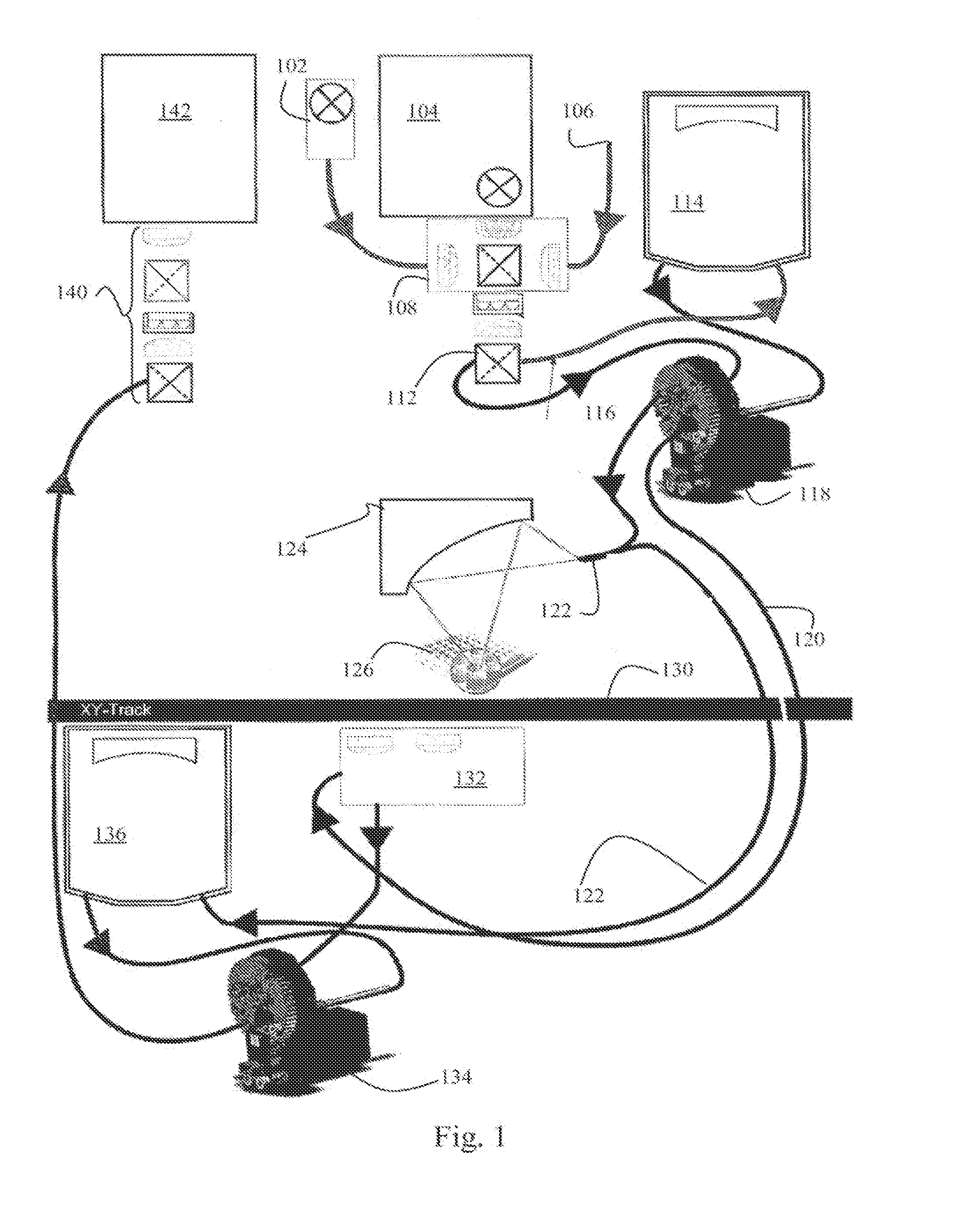
[0035]Referring to FIG. 1, the system comprises a multiple narrow-band light source module 102, which is used in fluorescence measurements. The module 102 is connected by an optical fiber or fiber bundle to a first light source selector module 108. To the first selector module 108 is also connected a wide-band light source 104. In this example, the selector module comprises also a third input 106 for a third light source type. The light is directed to a movable mirror 112, which is used for choosing the mode of operation. In absorbance measurements, wide-band light is conveyed to a sample site of a microtiter plate 126. In fluorescence measurement, narrow-band light is conveyed to a monochromator 114, from which the light is further guided to the sample site of the microtiter plate 126.

[0036]For selecting whether the absorption / excitation light is directed to the sample site from above or from below, a light relay 118 is provided in the optical path between the mirror 112 and the mi...


PUM

PropertyMeasurementUnit
wavelength bandsaaaaaaaaaa
widthaaaaaaaaaa
widthaaaaaaaaaa

Abstract

An apparatus for optically analyzing samples contained in sample sites of a sample holder, the apparatus has a first light source and at least one second light source, a monochromator having an input to which first light source is optically connected or connectable and an output for monochromatized light, light guiding portion for guiding light originating from the first and from the at least one second light sources to the sample sites, and a detector for detecting light from the sample sites. A light relay having a first input optically connected to the output of the monochromator, at least one second input optically connected or connectable to a second light source such that the light from the second light source by-passes the monochromator, and a first output for guiding light from selected input of the light relay to the sample sites. Based on the apparatus and light relay a versatile sample analyzer can be achieved in a cost-effective manner.

Description

BACKGROUND OF THE INVENTION[0001]1. Field of the Invention[0002]The invention relates to optical sample detectors used in various fields of life and analytical sciences, in particular medical and biomedical assays. In particular, the invention relates to sample analysers capable of fluorescence measurements.[0003]2. Prior Art[0004]Analysers of the present kind are commonly adapted to detect light successively from each one of a plurality of sample sites contained in the microplate. Therefore, they are frequently called as microplate “readers”. One example or such a system is the EnVision-reader and its variants available from PerkinElmer.[0005]The present commercial microplate readers typically include a broad-band excitation light source. Different kinds of optical arrangements for manipulating and guiding light from the light source to the sample sites are disclosed in US 2003 / 0081207, U.S. Pat. No. 6,232,608, WO 00 / 63680, US 2002 / 0109841, U.S. Pat. No. 6,313,471, WO 2005 / 057187, ...

Claims


Application Information

Patent Timeline
Patent Type & Authority Patents(United States)
IPC IPC(8): G01N21/25G01J3/44G01J3/12G01J3/42G01J3/02G01J3/10G01N21/64G02B6/42
CPCG01N21/253G01N2021/6484G01J3/12G01N2021/6491G01J3/42G01N21/6452G01J3/44G01J3/10G01J3/0218G01N21/6408G02B6/4298G01N2021/6439
Inventor LAITINEN, JYRKIKIVELA, PETRI
Owner WALLAC
Why Eureka
Try Eureka