
System and method for common path pessimism reduction in timing analysis to guide remedial transformations of a circuit design

a technology of common path pessimism and timing analysis, applied in the field of electronic design automation, can solve the problems of overly pessimistic timing characteristics, inordinate turn around time, overly burdensome storage, processing and memory requirements, etc., and achieve the effect of reducing unwarranted physical corrections

Active Publication Date: 2014-06-03
CADENCE DESIGN SYST INC
View PDF15 Cites 34 Cited by
  • Summary
  • Abstract
  • Description
  • Claims
  • Application Information

AI Technical Summary

Benefits of technology

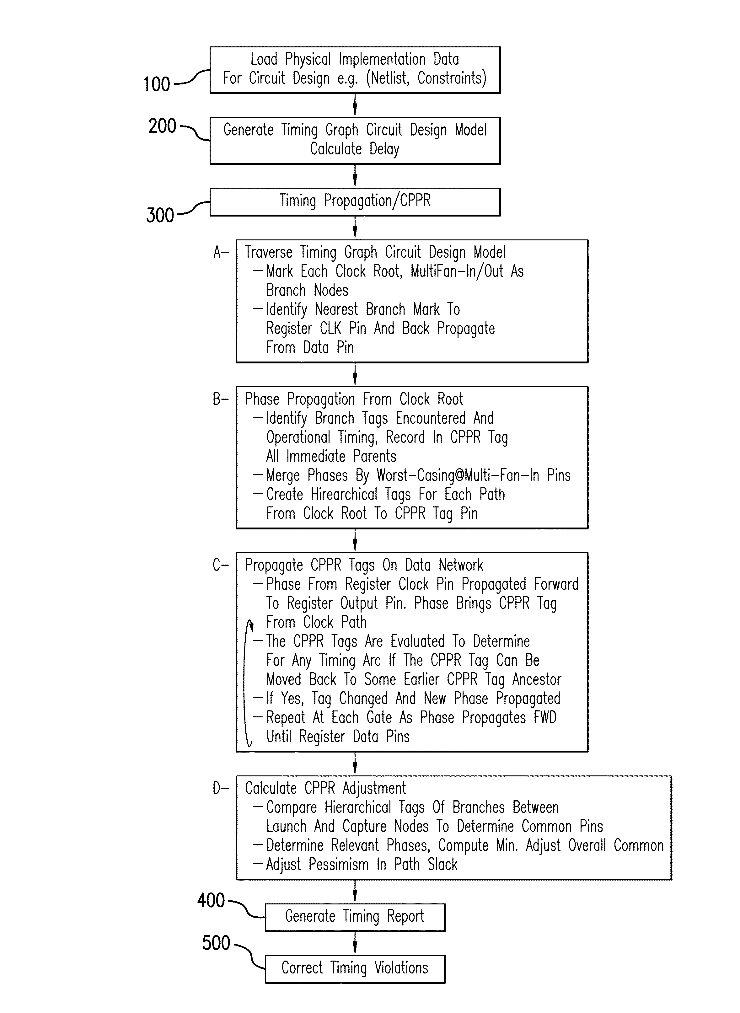
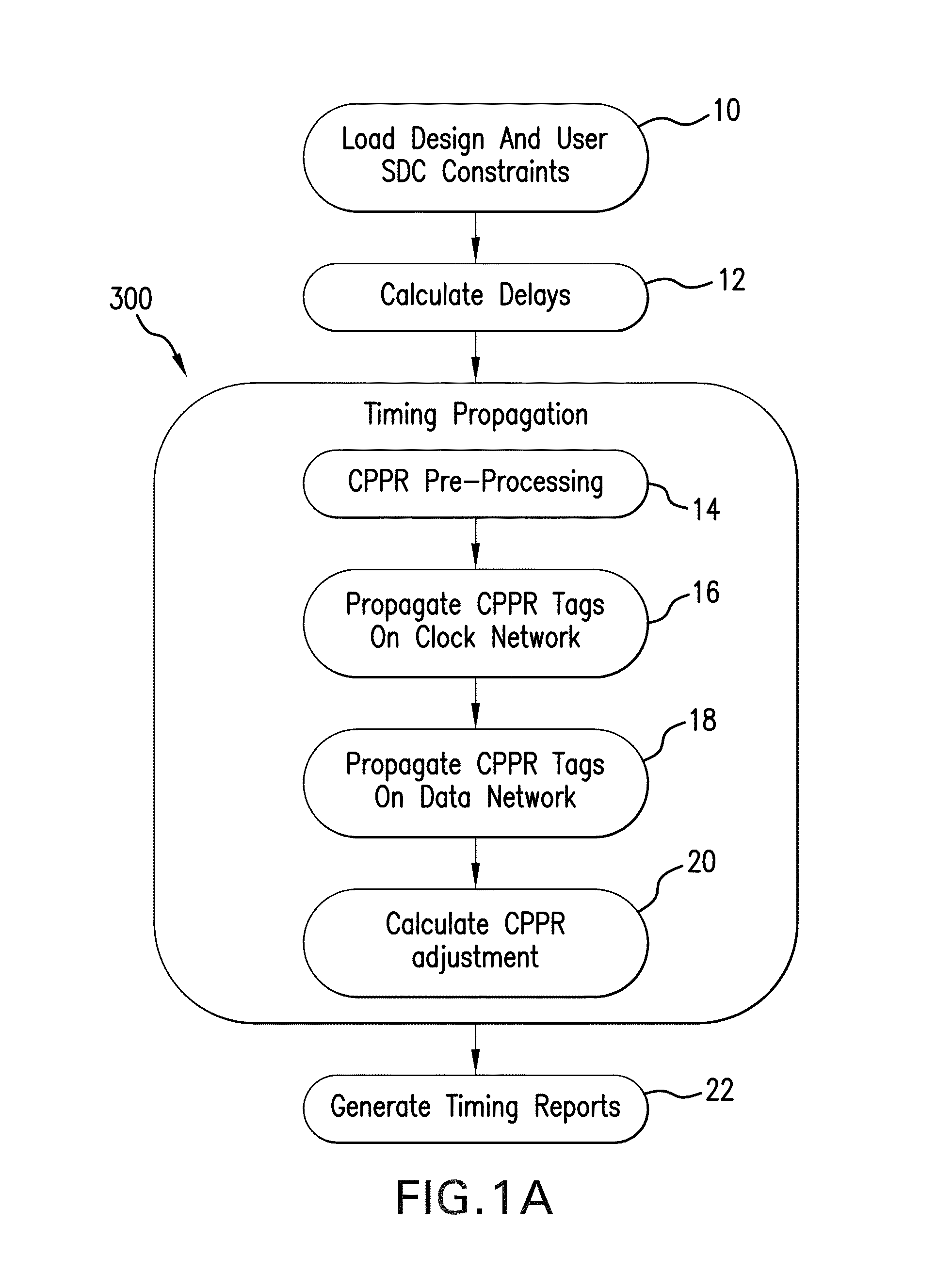
This patent describes a system and method for improving the analysis and design of circuit designs. It aims to reduce common path pessimism, which can cause unwarranted physical corrections for false-positive violations in circuit designs. The system and method use a timing model to define paths and interconnection points in the circuit design, and a common ancestor identification module to identify portions of the circuit that are shared between two paths. A common path pessimism reduction module then selectively sets a timing delay parameter for the clocked devices to compensate for the shared path portions, in order to avoid delay pessimism and improve the overall timing analysis of the circuit design.

Problems solved by technology

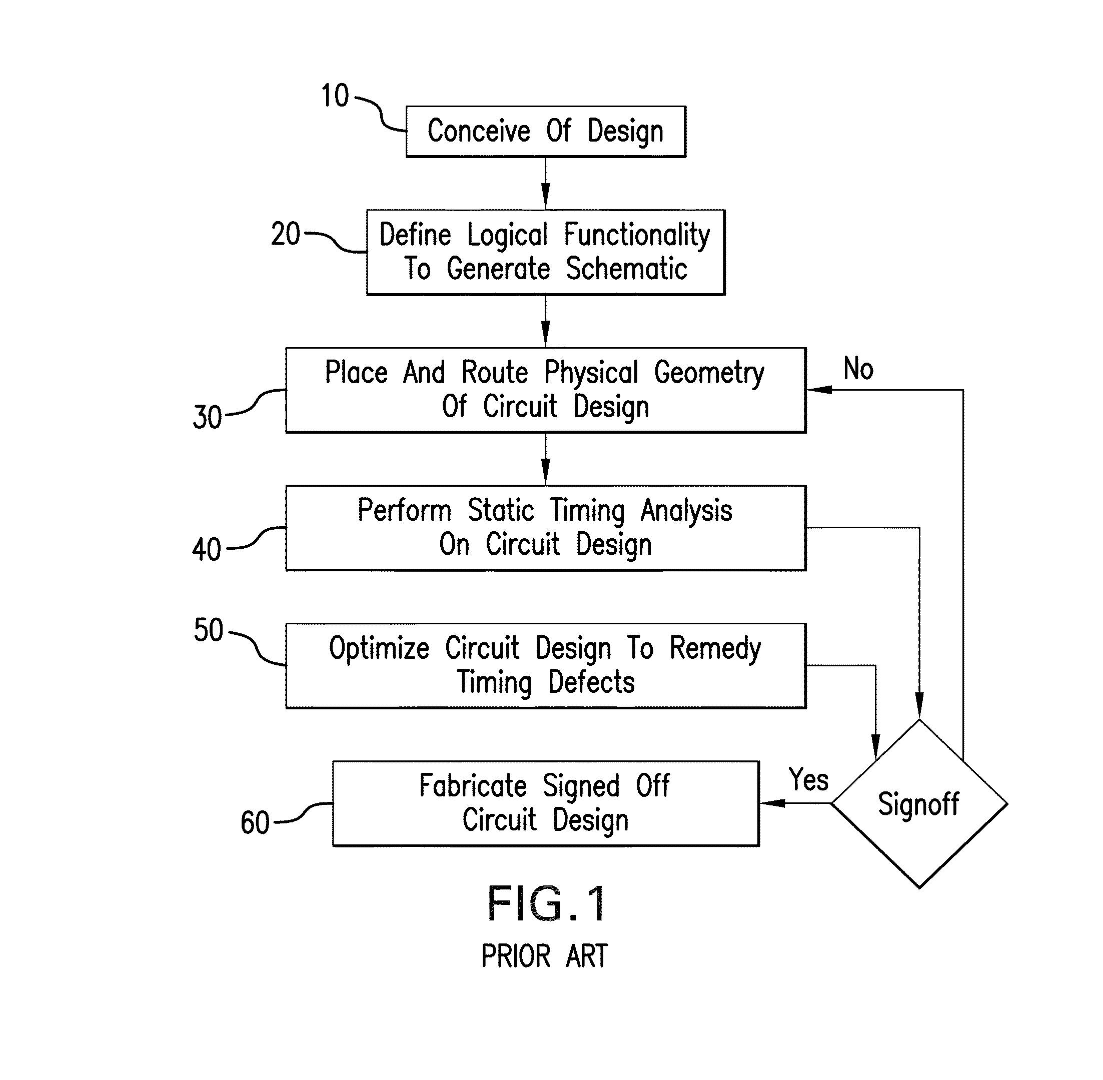
While signoff systems and methods are known, such heretofore known systems and methods are encumbered by numerous deficiencies, not the least of which are required repeated transformative iterations between timing signoff and physical implementation / optimization.
Other deficiencies include highly divergent timing analyses between timing signoff and physical implementation optimizers—which lead to overly pessimistic timing characteristics and attendant false-positive violations (requiring over-fixing of the circuit design), inordinate turn around time, and overly burdensome storage, processing, and memory requirements.
Such deficiencies have heretofore hindered efforts to minimize circuit product fabrication costs, time to market, power requirements, and substrate area while maximizing performance.

Method used


Image

  • System and method for common path pessimism reduction in timing analysis to guide remedial transformations of a circuit design
  • System and method for common path pessimism reduction in timing analysis to guide remedial transformations of a circuit design
  • System and method for common path pessimism reduction in timing analysis to guide remedial transformations of a circuit design

Examples


Embodiment Construction

[0024]The subject system and method generally provide measures for removing undue pessimism or conservatism from a timing database resulting from a static timing analysis (STA) of a circuit design. The subject system and method serve to thereby remove unwarranted timing violation detections and reduce corrective physical transformations ordered for the circuit design.

[0025]Along an electronic design flow, for example, an electronic design automation (EDA) flow, a circuit design is conceived and elaborated typically through numerous computer-aided stages to arrive at a physical circuit design layout. The layout defines actual coordinates and physical geometries for each component of the given circuit design and interconnections therebetween for ultimate fabrication as an operable, tangible, IC product.

[0026]An exemplary electronic design automation (EDA) flow traverses recursively through a plurality of stages towards the actual fabrication of complex integrated circuit devices, micr...


PUM


Abstract

A system and method are provided for common path pessimism removal or reduction (CPPR) in a timing database provided to guide transformative physical optimization / correction of a circuit design for an IC product to remedy operational timing violations detected in the circuit design. Pessimism is reduced through generation of a common path pessimism removal (CPPR) tree structure of branching nodes, and operational timing characteristics of each node. The CPPR tree structure is used to avoid exponential phases propagating in an exploratory manner through the system design, as well as the resultant memory footprint thereof. Additionally, back-tracing node-by-node through the circuit design for each and every launch and capture flip flop pair end point through each possible path thereof is avoided.

Description

RELATED APPLICATIONS[0001]This Application is a Non-provisional Patent Application of U.S. Provisional Application 61 / 800,325 filed 15 Mar. 2013, now pending.BACKGROUND OF THE INVENTION[0002]The present invention is generally directed to electronic design automation (EDA) for creating integrated circuit (IC) products, such as, for example, system on-chip (SOC) IC products and the like. More specifically, the present invention is directed to providing expeditious timing sign-off verification and correction with minimal fixing and minimal engineering change order (ECO) looping during sign-off of a physical circuit design. In certain applications, the present invention is directed to common path pessimism removal (CPPR) in a timing database to guide optimizer transformations of the circuit design to remedy timing violations detected therein.[0003]While signoff systems and methods are known, such heretofore known systems and methods are encumbered by numerous deficiencies, not the least...

Claims


Application Information

Patent Timeline
IPC IPC(8): G06F17/50
CPCG06F17/5068G06F17/5031G06F2217/84G06F30/3312G06F2119/12G06F30/00G06F30/3315
Inventor GARG, VIBHORBELKHALE, KRISHNAKULSHRESHTHA, PAWANYALCIN, HAKAN
Owner CADENCE DESIGN SYST INC
Learn More