Tiltable vacuum loader and receiver with blow-back

a technology of vacuum loader and receiver, which is applied in the direction of packaging, liquid/fluent solid measurement, and opening closed containers, etc., can solve the problems of interrupting the operation, interrupting the operation, and reducing so as to improve reduce the amount of air, and facilitate cleaning. , the effect of improving the reliability of the loader

Inactive Publication Date: 2014-06-17
MAGUIRE STEPHEN B
View PDF80 Cites 34 Cited by
  • Summary
  • Abstract
  • Description
  • Claims
  • Application Information

AI Technical Summary

Benefits of technology

[0041]A major advantage of the invention in one of its aspects is that the bottom or dump flap of the tiltable loader may be weighted so that the flap closes naturally in response to gravity. With known loaders, static electricity may cause pellets of resinous material to tend to stick to the bottom flap. With the tiltable loader of the invention, when the air blast is supplied, the blast is so forceful that it pops open the dump flap, overcoming the counterbalance and clearing any pellets that have stuck to the dump flap due to static electricity or other effects. This greatly improves loader reliability since static electricity causing resin pellets to cling to the dump flap of conventional loaders can cause as many as one-third of the attempts to load resinous material to fail because the dump flap has not sealed, thereby defeating or severely compromising the vacuum draw of resinous material into the loader.
[0042]During operation of the tiltable loader, it is desirable to operate the air blast feature of the invention twice during each loading cycle. Typically, after a load of material has been released by the dump flap and the loader is empty, the vacuum motor starts to draw more material into the loader. Once second after the vacuum motor starts, the air blast is actuated thereby clearing any pellets that may have adhered to the dump flap, which could otherwise maintain the dump flap in the open position and defeat the action of the vacuum motor. The dump flap then closes due to the force of gravity acting on the counterbalance provided for the dump flap. Resin material continues to be loaded into the loader with control being effectuated by a timer. Once the timer has sensed that loading has continued for a sufficient period and the required amount of material has been loaded, the vacuum motor is turned off, loading stops and the vacuum level is allowed to drop whereupon resinous material in the loader is discharged as the dump flap opens and allows the material to flow downwardly into the process machine below. Then the air blast is actuated again to blow dust off the filter.
[0043]With the vertical orientation of the tiltable loader of the invention, the loader of the invention empties fully on a consistent basis, which is a problem with loaders that do not operate in a vertical orientation. Operation in a straight up, vertical orientation, together with the ability to unlatch and tilt the loader so that the material storage chamber can be accessed easily for cleaning, provides substantial operational efficiencies for plastic resin molders and extruders.
[0044]In still another one of its aspects, this invention embraces a vacuum loader for providing granular material to granular material processing equipment, where the loader preferably comprises a housing having a granular material intake and a granular material outlet. The granular material outlet facilitates downward gravity flow of granular material towards resin processing equipment. The loader further preferably comprises a latching web extending outwardly horizontally from the housing above the granular material outlet. A loader mounting plate is provided for positioning the loader on a horizontal surface. A latch mounting lug extends upwardly from the loader mounting plate. A latch is pivotally connected to the mounting lug and is rotatably movable relative thereto between two positions. The latch at a first position contacts the latching web and restrains the loader from tilting. The latch at a second position contacts the latching web and supports the loader when tilted. The latch is weighted to pivotally return to the first position when released.
[0045]An embodiment of the invention as disclosed in parent application Ser. No. 12 / 201,562 provides a high pressure accumulator chamber having a valve that is opened by applying air pressure to a diaphragm through action of a small solenoid. When the valve actuates, it snaps to a fully open position. Opening action of the valve in the this embodiment opens a passageway that is preferably about one (1″) inch in diameter, leading from an accumulator chamber to a vacuum loader filter to be cleaned.
[0046]The one inch diameter passageway is sufficiently wide that the resulting flow of air through the passageway is “explosive” and is effective as a cleaner, as the “explosive” flow of air uniformly distributes itself over the area of the filter for a brief moment. The result is a blowback device able to remove unwanted particles from the filter of a vacuum loader or other vacuum powered device.

Problems solved by technology

Otherwise the dust would be drawn through the vacuum system, eventually reaching and entering the vacuum motor or pump located downstream, and likely fouling the vacuum motor or pump, thereby disrupting operation of the vacuum system and necessitating shutdown of the molding or extrusion operation.
As with a receiver as described above, the filter keeps dust and other particulate matter, traveling with the pellets of granular plastic resin material, from entering the suction intake of the vacuum motor, fouling the motor and thereby interrupting operation.
As operation continues, dust and contaminants tend to clog the filter, reducing the amount of air that may be drawn by vacuum through the filter, thereby compromising operation of the vacuum motor in the case of a loader, or compromising the operation of the plant vacuum system in the case of a receiver.
However, the diaphragm valve / reservoir approach has limitations.
Typically, the air from the reservoir flows rather gently and acts on only a relatively small area of the filter, because flow of air into the portion of the loader or reservoir between the filter and the vacuum source is necessarily limited by the size and cross-sectional area of the valve, through which the air must pass.
While providing a larger valve is one possible solution to the problem, significant cost increases and material handling problems are associated with larger valves, such that this is not a viable approach.
Additionally the diaphragm valve approach often requires pilot valves, introducing more moving parts into the system, with a necessarily greater risk of failure.
Moreover the risk of rupture of the diaphragm is always present.
This again provides a costly and largely ineffective solution to this on-going problem plaguing the plastic fabrication industry.
A problem is that static electricity will cause resin pellets to cling to the dump flap.
The result is an air leak, poor vacuum being drawn and little or no loading occurring during that load cycle due to the lack of sufficient vacuum to draw material into the loader or receiver.
This approach does not always work and the gaskets degrade over time.
These pellet adhesion problems can account for loss of up to fifty percent (50%) of the operating time of the loader or receiver.
Tilted loaders are known and used because their tilted orientation facilitates cleaning, but they are less than satisfactory in that they do not empty consistently, especially if the material being loaded is not an easily flowing material.

Method used


Image

  • Tiltable vacuum loader and receiver with blow-back
  • Tiltable vacuum loader and receiver with blow-back
  • Tiltable vacuum loader and receiver with blow-back

Examples


Embodiment Construction

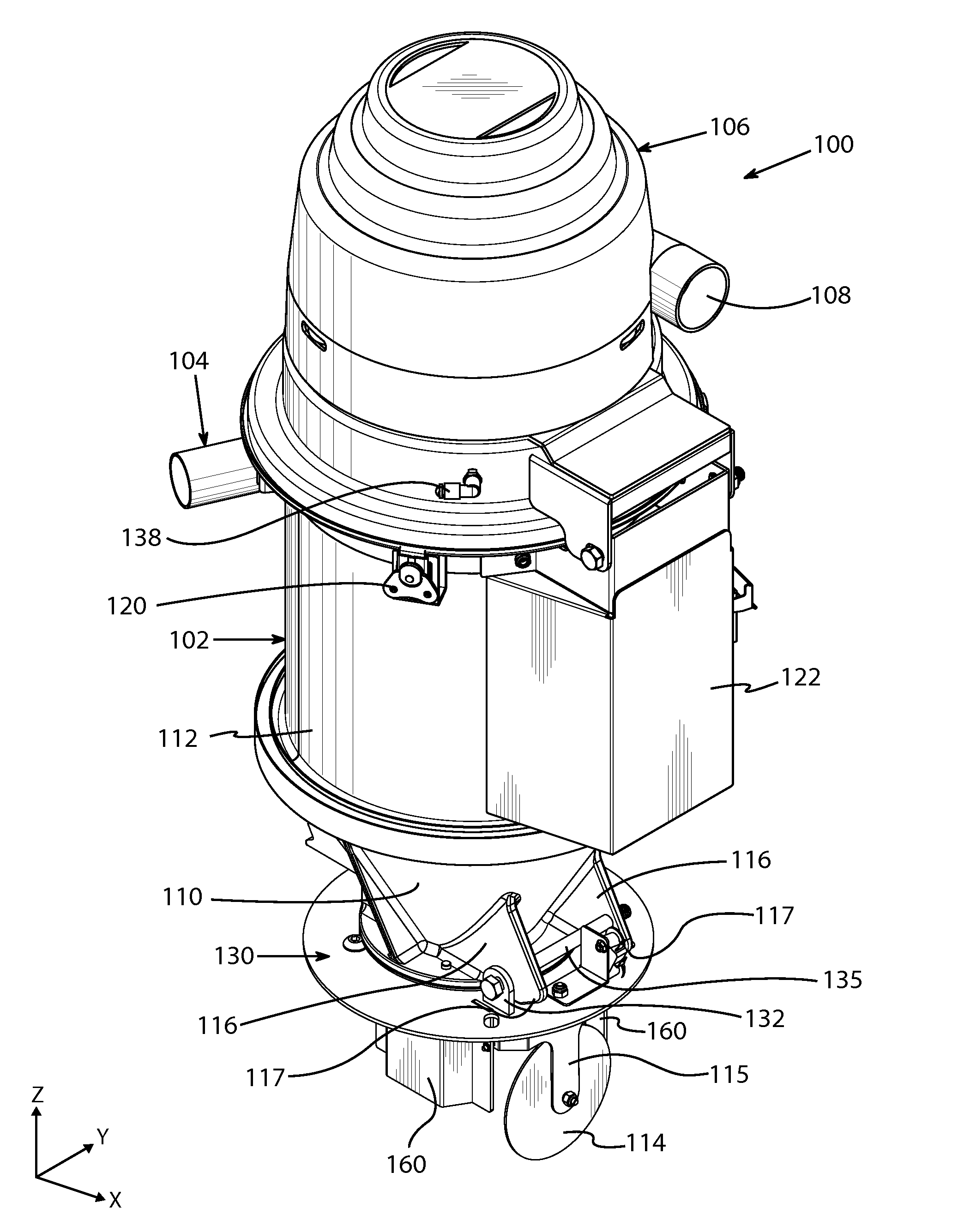
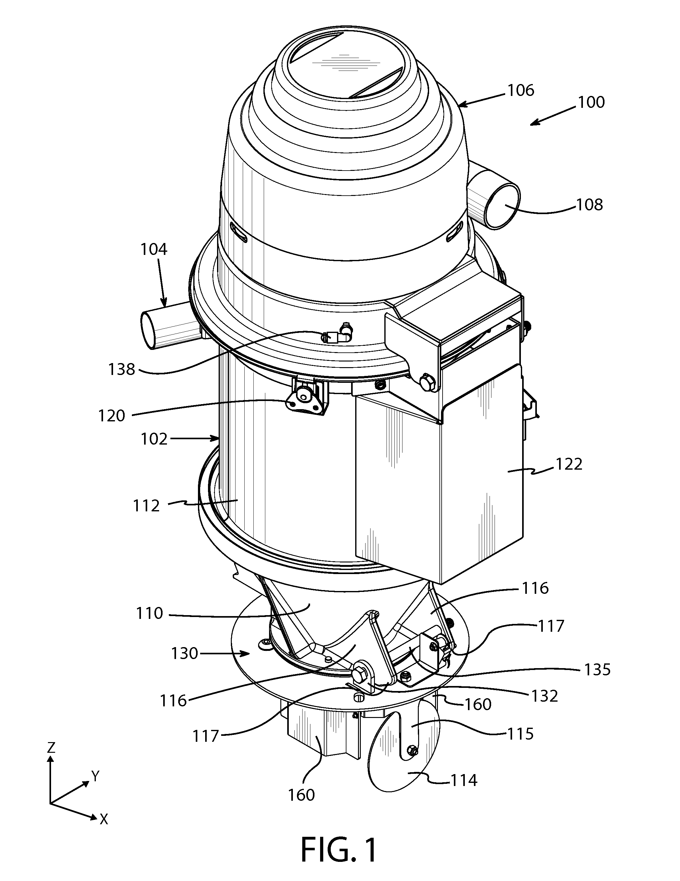
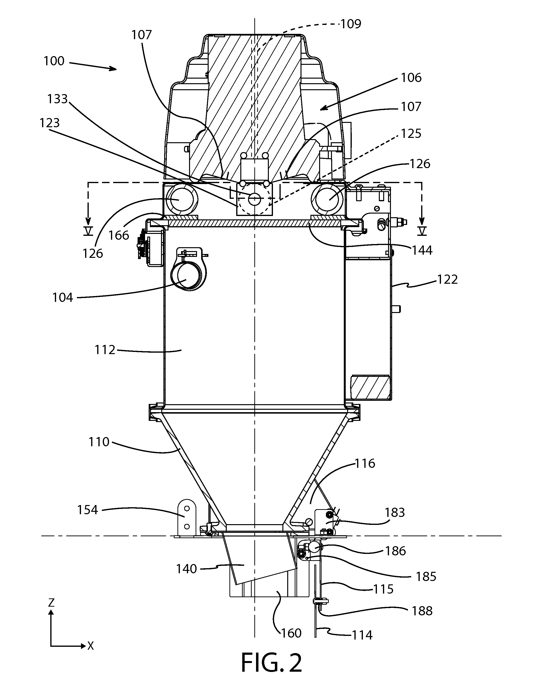
[0074]This invention provides apparatus and methods of providing blasts of compressed high pressure air to an air filter of a vacuum powered and vacuum conveying resin transport device wherein high pressure air is applied to a dust filter, in a direction opposite that through which air is drawn by the vacuum, to clear the filter of unwanted particles. The invention specifically provides an extremely compact “blowback” device using a minimum of moving parts to produce a blast of compressed air, in a reverse direction through the filter, to clear the filter of dust and to clear a dump flap of any resin material adhering thereto, and in the preferred embodiment does not employ any diaphragm valve, springs or solenoid actuation of the same. The air blast provided is substantial and of much greater force than can be achieved using one or more diaphragm valves at any reasonable cost.

[0075]Referring to the drawings in general, and to FIG. 1 in particular, a tiltable vacuum loader embodying...


PUM

PropertyMeasurementUnit
timeaaaaaaaaaa
diameteraaaaaaaaaa
diameteraaaaaaaaaa

Abstract

A vacuum loader for providing granular resin material to resin material processing equipment has a loader housing, a vacuum motor, a dust filter, an air blast generator, a dump flap, and a pivoting manually releasable latch for retaining the lateral web and the loader from tilting rotation of the loader about the shaft and supporting the loader when placed in a tilted orientation; the latch being weighted to pivotally return to a web-retaining position when released by an operator.

Description

CROSS REFERENCE TO RELATED PATENT APPLICATIONS[0001]This patent application is a 35 USC 120 continuation-in-part of U.S. patent application Ser. No. 12 / 201,562, filed 29 Aug. 2008 and published as US2009 / 0126564 A1 on 21 May 2009, now U.S. Pat. No. 8,070,844 B2 which claims the priority of U.S. provisional patent application Ser. No. 60 / 967,065 filed 31 Aug. 2007.[0002]This application claims the priority of U.S. Ser. No. 12 / 201,562 under 35 USC 120 and of U.S. Ser. No. 60 / 967,065 under 35 USC 119 and 120.[0003]The disclosures of U.S. Ser. No. 60 / 967,065 and U.S. Ser. No. 12 / 201,562 are hereby incorporated by reference.BACKGROUND[0004]1. Field of Invention[0005]This invention relates to apparatus and methods for applying a blast of compressed air to an air filter of a granular plastic resin vacuum loader or receiver into which resin conveyance is powered by vacuum.[0006]The invention further relates to apparatus and methods to dislodge resin pellets that may have stuck at the bottom...

Claims


Application Information

Patent Timeline
Patent Type & Authority Patents(United States)
IPC IPC(8): B01D46/04
CPCB65G53/24B65G65/34B65G53/40Y10T137/0396Y10T137/71
Inventor MAGUIRE, STEPHEN, B.
Owner MAGUIRE STEPHEN B
Why Eureka
Try Eureka