

Rotor for rotary electric machine with reduced-mass interpolar structures
a technology of interpolar structure and rotor, which is applied in the direction of dynamo-electric machines, electrical apparatus, magnetic circuits, etc., can solve the problems of creating a magnetic obstacle, reducing the volume of magnets which would not be useful, etc., and achieves the elimination of the volume of magnets, reducing the mass of magnets, and limiting the leakage of magnetic flow
- Summary
- Abstract
- Description
- Claims
- Application Information
AI Technical Summary
Benefits of technology
Problems solved by technology
Method used
Image

Examples
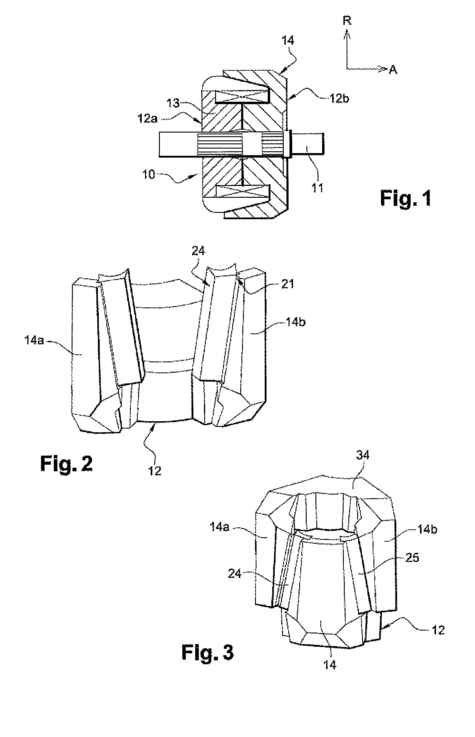
first embodiment
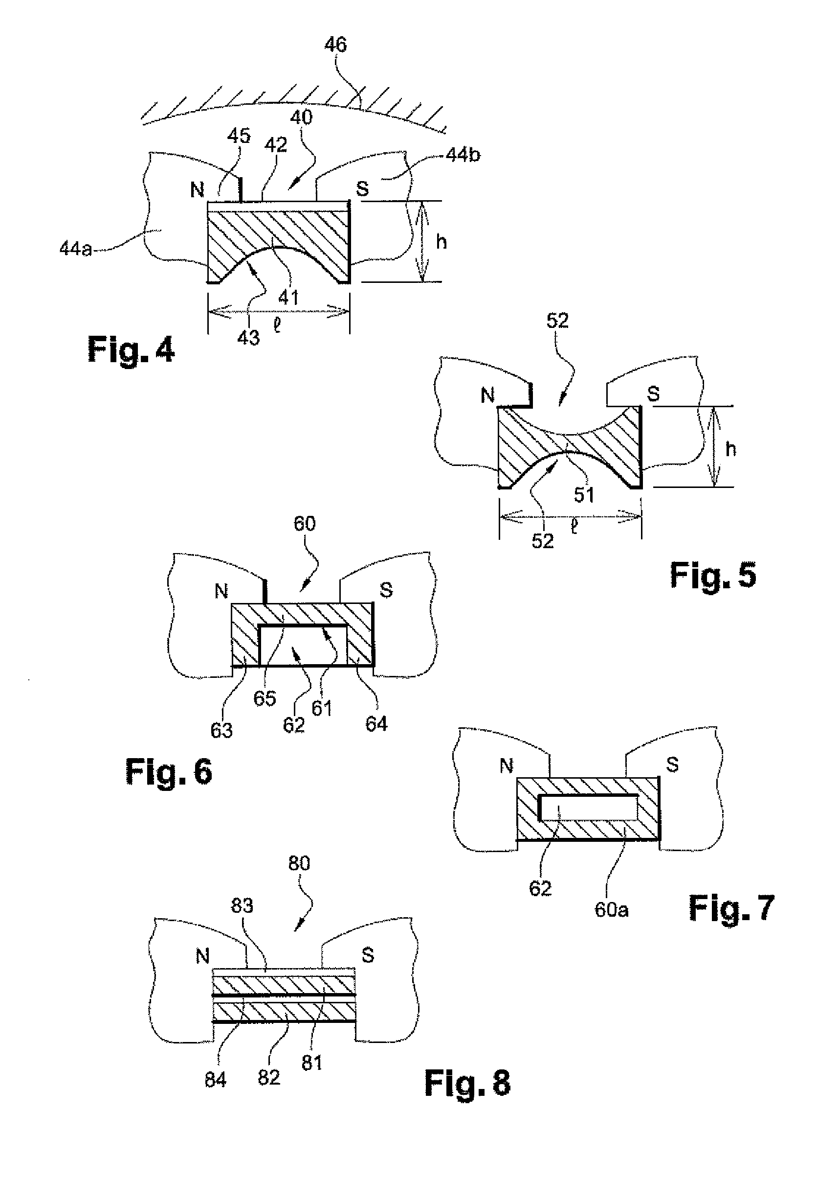
[0063]In the magnetic assembly 40 in FIG. 4, the magnetic assembly 40 consists both of a magnet 41 and an element made of magnetic material 42.
[0064]The magnet 41 is preferably made of rare earth material. For example, it can be obtained by moulding or machining a basic block (for example by milling). With reference to its implantation in the interpolar gaps of the rotor, the magnet 41 has a base in the form of a parallelepiped with an axial length L (not shown), with a circumferential width l, and a radial height h.
[0065]In this embodiment, on a face with dimensions L and l, the magnet is recessed along the entire axial length, from one end to the other.
[0066]On a radial cross-sectional plane, this recess 43 can have a profile which is semi-circular, elliptical or triangular, or it can have another shape. This recess can be centered relative to the face in which it is provided, or it can have another position. It can also have one or a plurality of recesses in the same face. The sh...
second embodiment
[0078]In the magnetic assembly in FIG. 6, the magnetic assembly 60 consists both of a magnet 61 and a magnetic element 62.
[0079]On a radial cross-sectional plane the magnet has a profile in the form of the letter “U”. This “U” is formed by 3 straight segments, and the radial segments 63 and 64 are substantially perpendicular to the longitudinal segment 65.
[0080]The magnetic element 62 is in the form of a parallelepiped, and its dimensions are such that it can easily be inserted in the hollow of the “U”.
[0081]The magnetic assembly 60 therefore has globally the form of a parallelepiped, and can thus easily be inserted between the grooves. The magnetic assembly presents to the claws faces which are constituted only by magnet, which improves its function of limitation of the magnetic leakages.
[0082]As a variant, as shown in FIG. 7, the magnet 60a can have the form of the letter “O”.
[0083]The magnet can be made in two parts, for example with two magnets which are joined by their ends, ea...
third embodiment
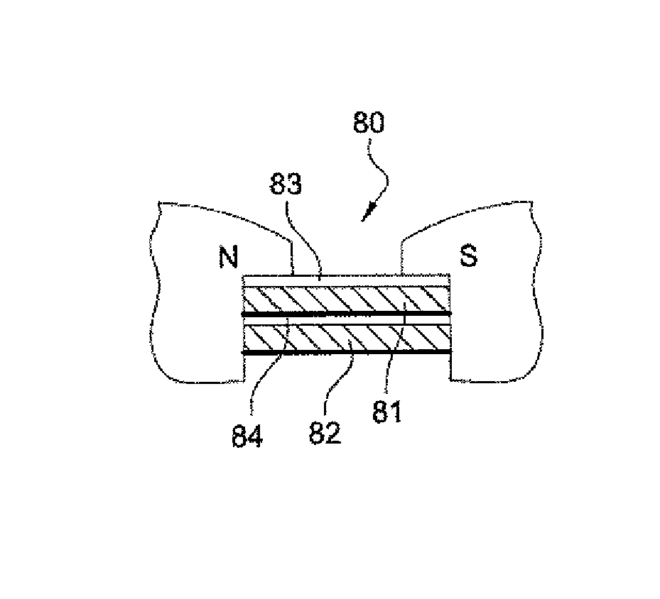
[0086]In the magnetic assembly in FIG. 8, the magnetic assembly 80 consists both of two magnets 81, 82 and two elements 83 and 84 made of magnetic material.
[0087]On a radial cross-sectional plane, the cross-section of the magnetic assembly 80 comprises an alternating succession of radial layers of magnet and magnetic material.
[0088]Thus, in FIG. 8, according to a radial direction, there is in succession a magnet 82 followed by an element 84 made of magnetic material, followed by another magnet 81, followed by a final element 83 made of magnetic material.
[0089]The magnets 81 and 82 have a globally parallelepiped form, and the elements 83, 84 which are made of magnetic material are thin plates.
[0090]FIG. 9 shows axial grooves (or shoulders) 21, each of which is provided in the lateral face of the claws 14 of the rotor. These claws belong to a single polar wheel 23. A magnetic assembly 24 is inserted in these grooves (or shoulders) such as to be in contact with both a claw 14 of a pola...
PUM
 Abstract
Description
Claims
Application Information