

Coating removal systems for optical fibers
a technology of optical fibers and removal systems, applied in the field of optical fibers, can solve the problems of reducing the service life of optical fibers, and causing significant debris, and achieve the effect of reliable optical communication and efficient removal
- Summary
- Abstract
- Description
- Claims
- Application Information
AI Technical Summary
Benefits of technology
Problems solved by technology
Method used
Image

Examples
Embodiment Construction
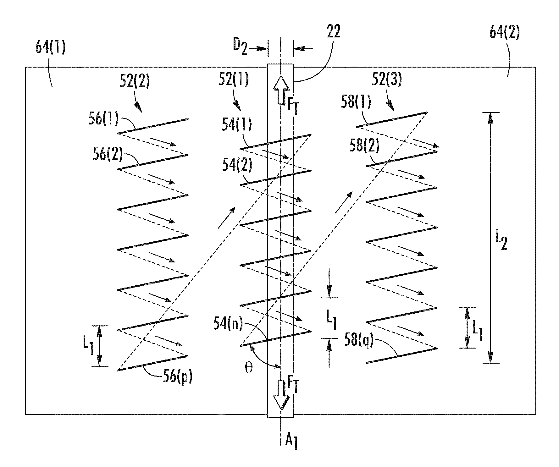
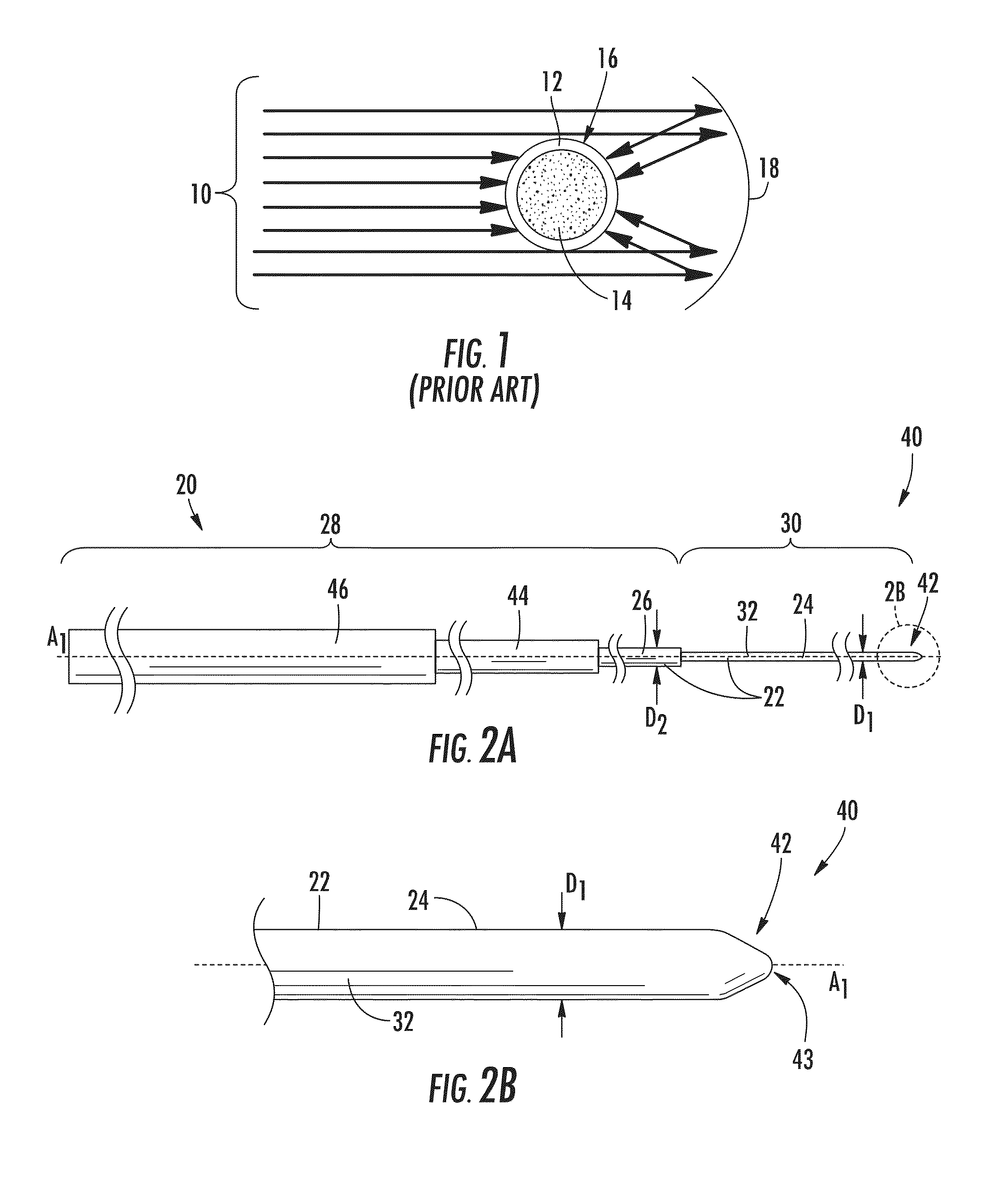
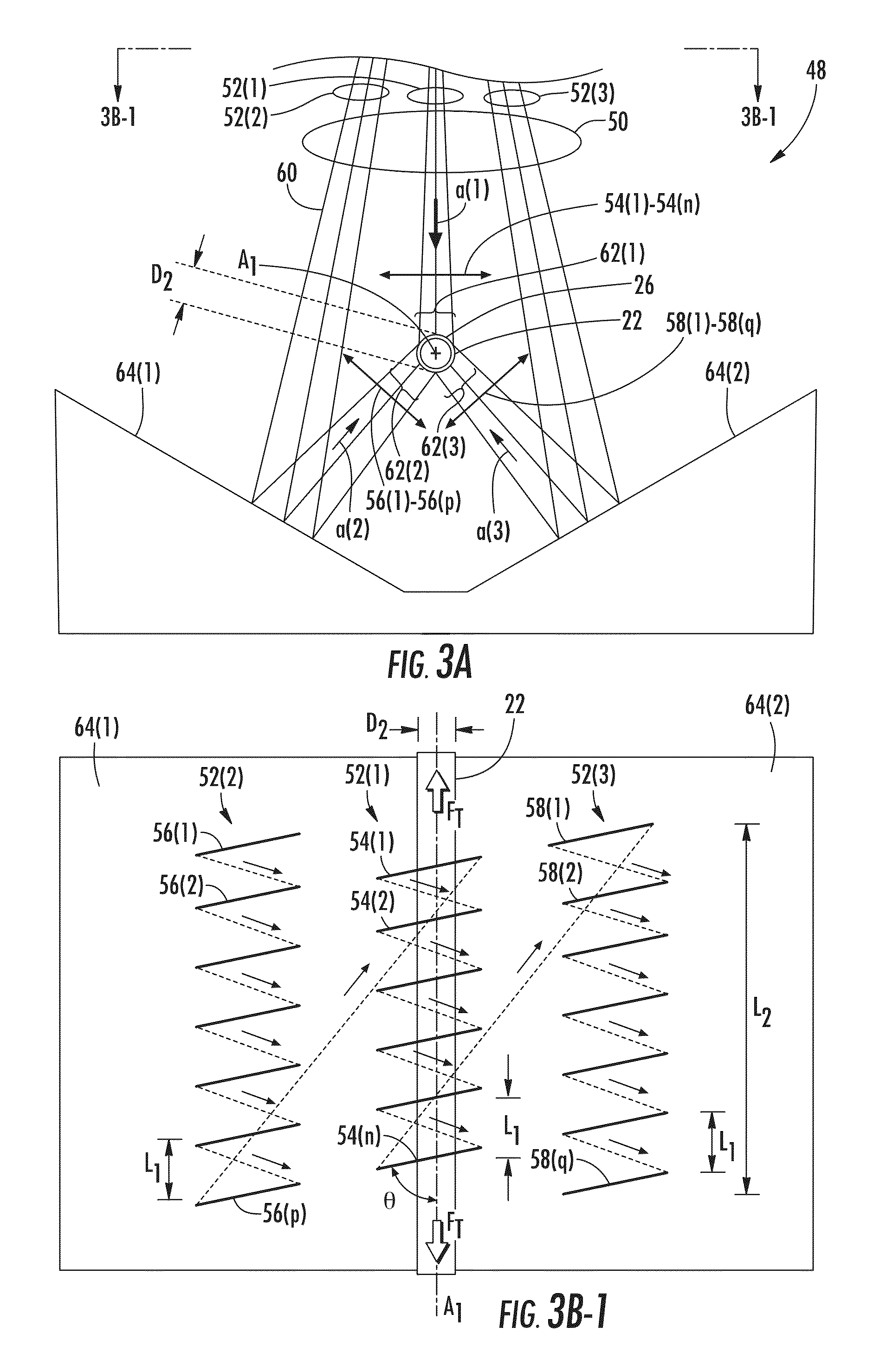
[0011]Embodiments disclosed herein include coating removal systems for optical fibers. Related methods and optical fibers processed with these methods and coating removal systems are also disclosed. An optical fiber includes a glass fiber, having a cladding and core, surrounded by a protective coating which does not contribute to the optical performance of the optical fiber. By removing the coating at an end portion of the optical fiber, the end portion may be precisely positioned and secured to enable reliable optical communications. A laser beam may be directed at the protective coating to remove the protective coating by one or more ablating, melting, vaporizing, and / or thermal decomposing processes. The optical fiber may also be optionally cleaved. In this manner, the coating may be efficiently removed while retaining at least fifty percent of the tensile strength of the optical fiber.
[0012]In one embodiment, a process for removing a polymer coating from a glass portion of an op...
PUM
| Property | Measurement | Unit |
|---|---|---|
| pitch distance | aaaaa | aaaaa |
| pitch distance | aaaaa | aaaaa |
| angle | aaaaa | aaaaa |
Abstract
Description
Claims
Application Information