Ultrasonic probe and ultrasonic diagnostic apparatus using the same

a technology of ultrasonic probes and diagnostic equipment, applied in the direction of mechanical vibration separation, instruments, applications, etc., can solve the problems of deterioration in insulation construction and insufficient insulation, and achieve the effect of preventing electric leakage to an obj

Active Publication Date: 2014-06-24
FUJIFILM HEALTHCARE CORP
View PDF13 Cites 67 Cited by
  • Summary
  • Abstract
  • Description
  • Claims
  • Application Information

AI Technical Summary

Benefits of technology

[0015]In accordance with the present invention, it is possible to provide an ultrasonic probe using a cMUT and an ultrasonic diagnostic apparatus using the same improved in electrical safety capable of preventing electric leakage to an object by providing adequate insulation configuration.BRIEF DESCRIPTION OF THE DIAGRAMS
[0016]FIG. 1 is a configuration diagram showing an ultrasonic diagnostic apparatus related to the present invention.
[0017]FIG. 2 is a configuration diagram showing an ultrasonic probe related to the present invention.
[0018]FIG. 3 is a configuration diagram showing a transducer related to the present invention.
[0019]FIG. 4 is a configuration diagram of one vibration element in FIG. 3 viewed from the side.
[0020]FIG. 5 shows an ultrasonic probe related to embodiment 1.

Problems solved by technology

However, in the ultrasonic probe using a cMUT, since the bias voltage is mainly applied to the electrode on the backing layer side at the same time as the driving signal formed by a high-frequency wave (drive voltage) is applied to the electrode on the object side, the ground layer cannot be contacted to the electrode on the object side directly, thus the insulation becomes insufficient unless a ground layer is provided.
Also, while there are cases in the ultrasonic probe using a cMUT that an acoustic matching layer is not provided, which causes the problem of deterioration in insulation construction.

Method used


Image

  • Ultrasonic probe and ultrasonic diagnostic apparatus using the same
  • Ultrasonic probe and ultrasonic diagnostic apparatus using the same
  • Ultrasonic probe and ultrasonic diagnostic apparatus using the same

Examples


embodiment 1

[0065]Next, embodiment 1 of the present invention will be described referring to FIG. 5 and FIG. 6.

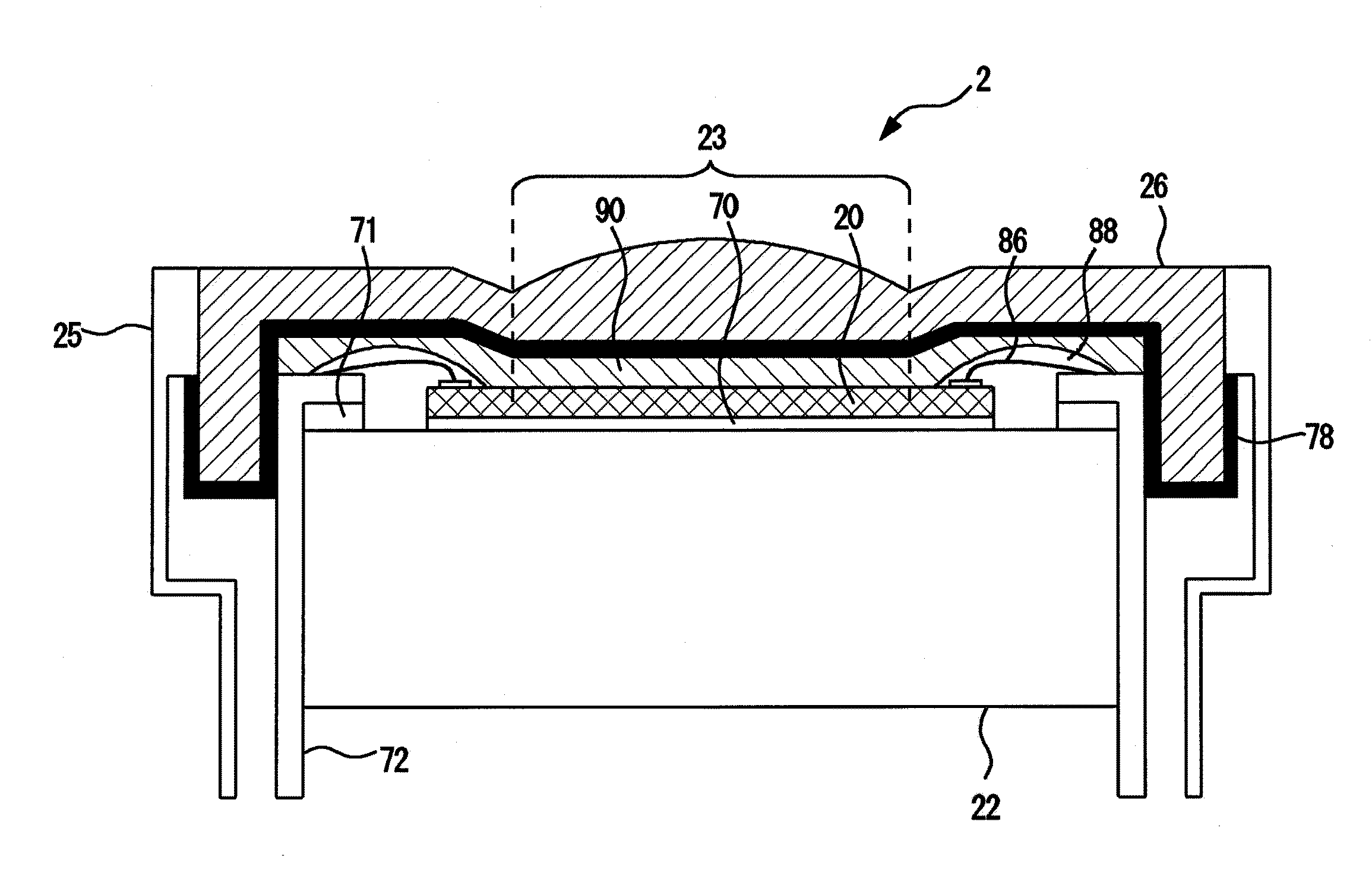
[0066]FIG. 5 shows the ultrasonic probe 2 related to embodiment 1. FIG. 5 is a cross-sectional view of the flat plane “A” of the ultrasonic probe 2 shown in FIG. 2.

[0067]In accordance with FIG. 5, an insulating film 78 which is an insulation layer is formed on the back surface of the acoustic lens 26. The insulating film 78 is, for example, a silicon oxide film or a paraxylene film.

[0068]The cMUT chip 20 is glued to the upper surface of the backing layer 22 via the adhesion layer 70. A flexible substrate 72 (Flexible printed circuits: FPC) is provided from the peripheral border of the upper surface of the backing layer 22 over to the side surfaces in four directions. The flexible substrate 72 is glued onto the peripheral border of the upper surface of the backing layer 22 via the adhesion layer 71.

[0069]The adhesion layer 70 and the adhesion layer 71 are an adhesive agent formed by, fo...

embodiment 2

[0084]Next, embodiment 2 will be described referring to FIG. 7.

[0085]FIG. 7 shows an ultrasonic probe 2a related to embodiment 2. FIG. 7 is equivalent to the cross-sectional view of the flat plane “A” shown in FIG. 2.

[0086]While the insulation film 78 is illustrated as being disposed in the lower surface of the acoustic lens in embodiment 1, the insulation layer which is electric leakage preventing means for preventing the leakage of electricity from the electrode in the cMUT chip to the object is disposed in the upper surface (object side) of the acoustic lens 26 as an insulation film 78a in embodiment 2.

[0087]In this manner, in the ultrasonic probe 2a of embodiment 2, the insulation layer is formed in the upper surface of the acoustic lens. The spacing between the ultrasonic wave transmitting / receiving surface and the cMUT chip is performed with double insulation by the insulation layer (insulation film) and the acoustic lens. Therefore, even when friction or damage is caused in t...

embodiment 3

[0089]Next, embodiment 3 will be described referring to FIG. 8.

[0090]FIG. 8 shows an ultrasonic probe 2b related to embodiment 3. FIG. 8 is equivalent to the cross-sectional view of the flat plane “A” shown in FIG. 2.

[0091]While the insulation film 78 is described as being disposed on the lower surface of the acoustic lens 26 in embodiment 1, the insulation layer which is electric leakage preventing means for preventing the leakage of electricity from the electrode in the cMUT chip to the object is disposed on the upper surface of the cMUT chip 20 as an insulation film 78b in embodiment 3.

[0092]In this manner, in the ultrasonic probe 2b of embodiment 3, the insulation layer is formed on the upper surface of the cMUT chip. In the spacing between the ultrasonic wave transmitting / receiving surface and the cMUT chip, double insulation is performed by the insulation layer and the acoustic lens. Thus the same effect can be performed as embodiment 1.


PUM


Abstract

An ultrasonic probe is disclosed which includes a cMUT chip having a plurality of vibration elements whose electromechanical coupling coefficient or sensitivity is changed according to a bias voltage and transmitting and receiving ultrasonic waves, an acoustic lens arranged above the cMUT chip, and a backing layer arranged below the cMUT chip. An electric leakage preventing unit is provided at the ultrasonic wave transmission / reception surface side of the acoustic lens or between the acoustic lens and the cMUT chip. The electric leakage preventing unit can be, for example, an insulating layer such as a ground layer. Such a structure makes it is possible to provide an ultrasonic probe capable of preventing electric leakage from the ultrasonic probe to an object to be examined so as to improve the electric safety and an ultrasonic diagnostic apparatus using the probe.

Description

TECHNICAL FIELD[0001]The present invention relates to an ultrasonic probe and ultrasonic diagnostic apparatus using the same, and more particularly to an ultrasonic probe and ultrasonic diagnostic apparatus using the same wherein the electric safety for an object to be examined is improved.BACKGROUND ART[0002]An ultrasonic diagnostic apparatus is for imaging diagnostic images based on the echo signals and the reflected signals thereof outputted from an ultrasonic probe. In an ultrasonic probe, a plurality of ultrasonic transducers is disposed. The ultrasonic transducers convert driving signals into ultrasonic waves and transmit them to the object, as well as receive the reflected echo signals produced from the object and convert them into electric signals.[0003]In recent years, ultrasonic probes using a cMUT (Capacitive Micromachined Ultrasonic Transducer) have been developed. The cMUT is an ultrafine capacitance ultrasonic transducer manufactured by semiconductor microfabrication p...

Claims


Application Information

Patent Timeline
Patent Type & Authority Patents(United States)
IPC IPC(8): A61B8/14A61B8/00
CPCA61B8/4281A61B8/4455A61B8/4483B06B1/0292H04R19/005
Inventor SANO, SHUZOSAKO, AKIFUMIKOBAYASHI, TAKASHIIZUMI, MIKIO
Owner FUJIFILM HEALTHCARE CORP
Why Eureka
Try Eureka