Multi-component bladed rotor for a turbomachine

a turbomachine and multi-component technology, applied in the direction of liquid fuel engines, vessel construction, marine propulsion, etc., can solve the problems of increasing material, manufacturing and assembly costs, and achieve the effects of preventing a weakening of the rotor structure, facilitating separation, and advantageously eliminating production and assembly costs for filling pieces

Active Publication Date: 2014-07-22
MAN ENERGY SOLUTIONS SA
View PDF22 Cites 5 Cited by
  • Summary
  • Abstract
  • Description
  • Claims
  • Application Information

AI Technical Summary

Benefits of technology

The patent text describes a way to make filling pieces without worrying about production and assembly costs. It also prevents weakening of the rotor and interference in the flow of force. Additionally, it makes it easier to manufacture and monitor the groove that is formed.

Problems solved by technology

This disadvantageously increases cost on material, manufacturing and assembly because this free space must be closed with a corresponding filling piece when the rotor is assembled in order to prevent interference of the flow.

Method used


Image

  • Multi-component bladed rotor for a turbomachine
  • Multi-component bladed rotor for a turbomachine
  • Multi-component bladed rotor for a turbomachine

Examples


Embodiment Construction

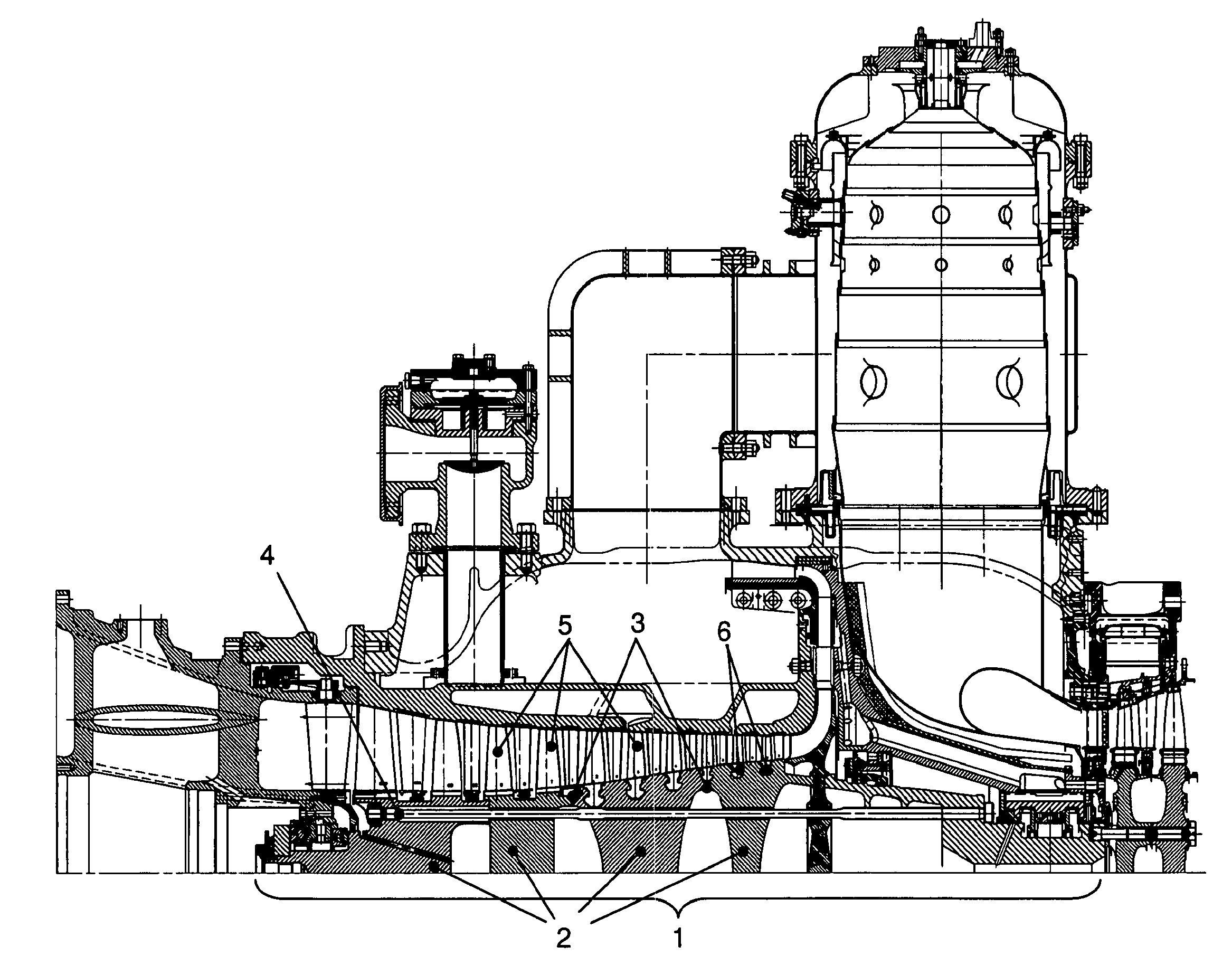
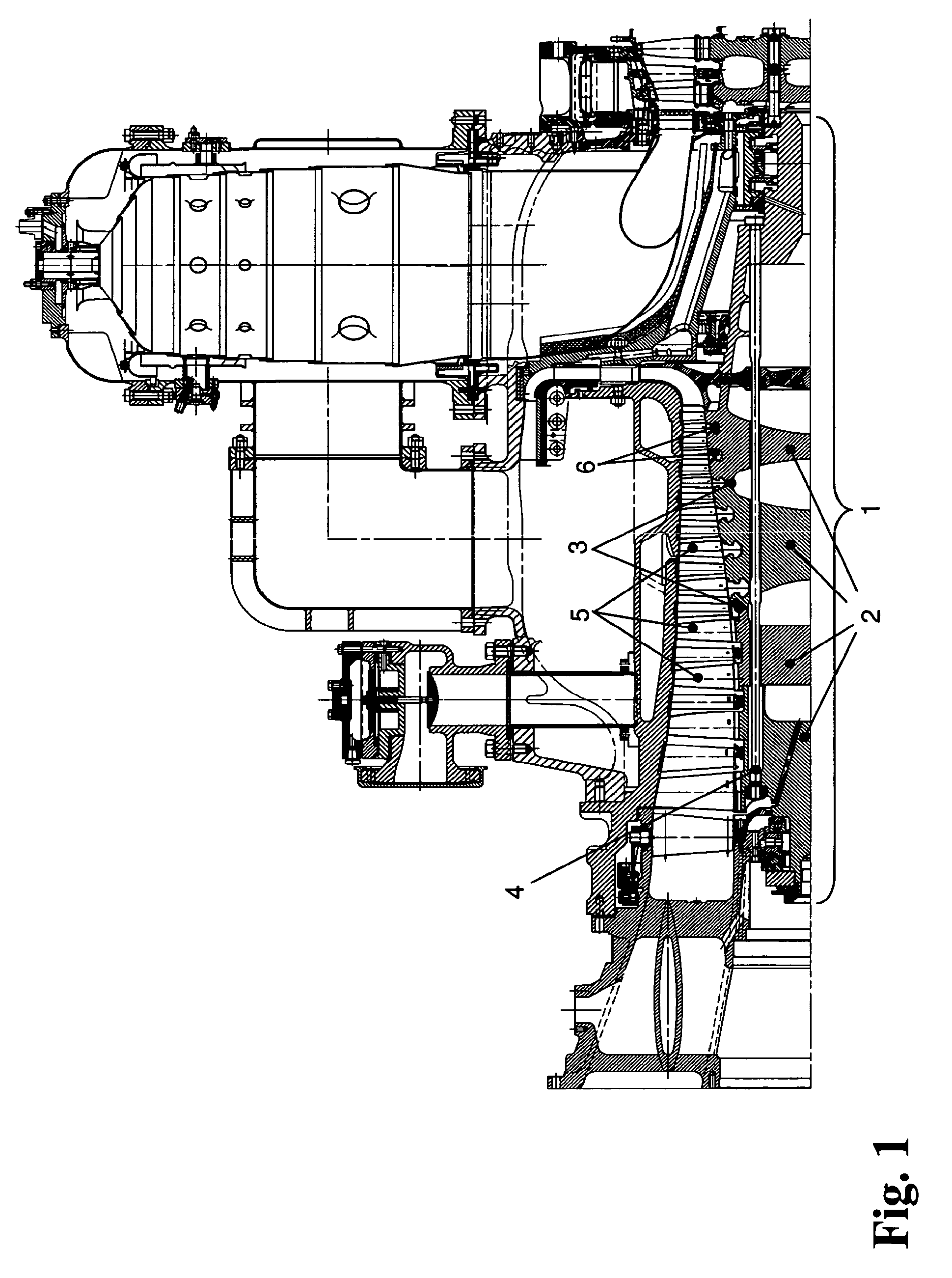
[0027]The disks 2 are positioned relative to one another by means of Hirth-type spur teeth 3 or Gleason-type teeth and are clamped by screws or tie rods 4 to form a rotor composite.

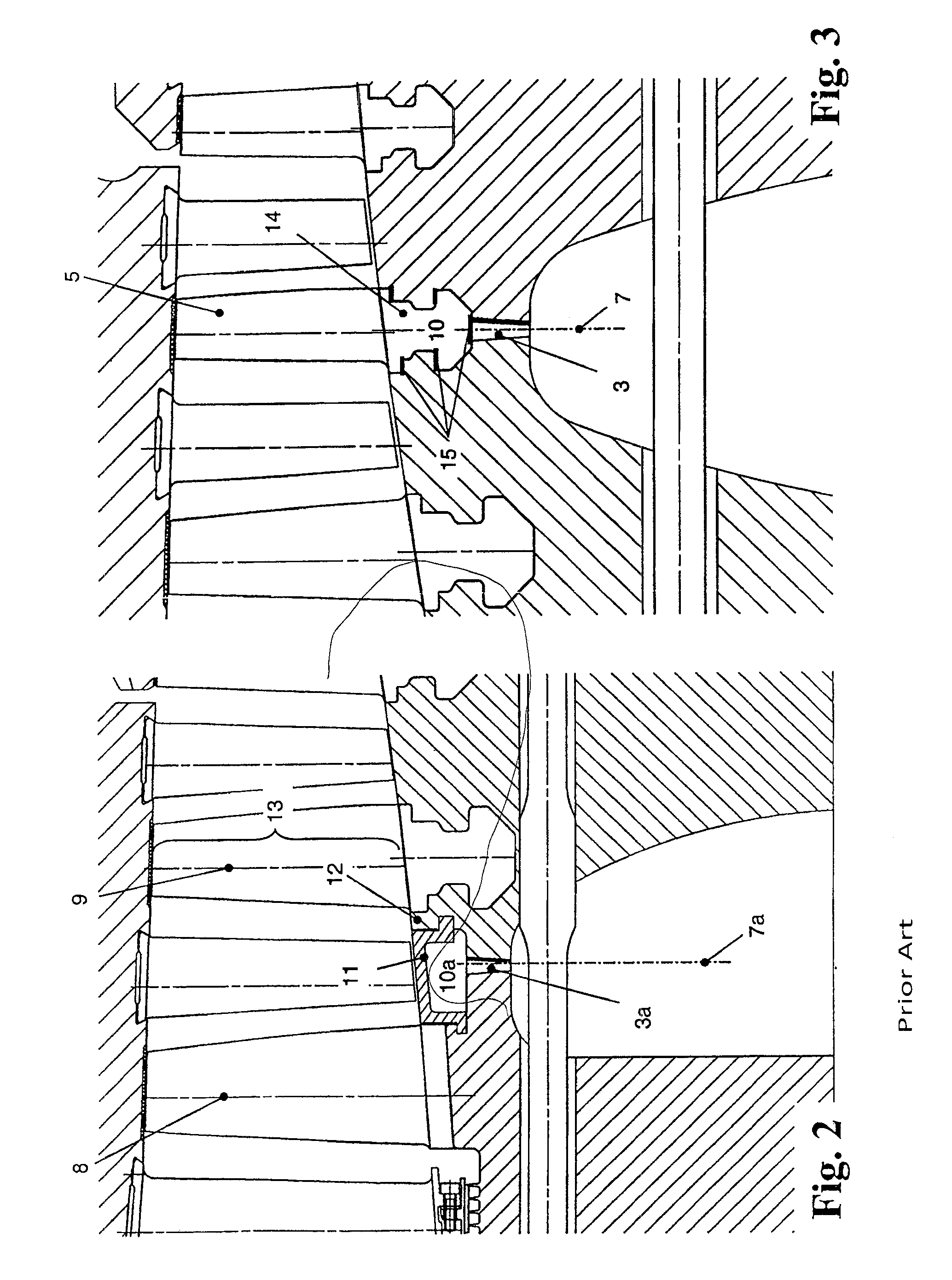
[0028]In a rotor according to the prior art, a section of which is shown in FIG. 2, the separating planes 7a of the multidisks are arranged between grooves of two adjacent blade rows 8 and 9. Since the Hirth-type spur toothing 3a is arranged on a diameter which is smaller than the outer diameter of the compressor disks, a corresponding free space 10a must be provided to allow for the withdrawal of the tool for the process of producing the toothing 3a. This free space 10a must be closed with corresponding filling pieces 11 when assembling the rotor to ensure a continuous hub contour and, therefore, a continuity of the inner wall 12 of the flow channel 13 of the gas turbine.

[0029]In a rotor according to an embodiment of the present invention, shown in FIG. 3, such as can be used, for example, in a gas turbi...


PUM


Abstract

A multipart bladed rotor (1) for a flow machine, particularly a gas turbine or steam turbine or an axial compressor, has at least two disks (2) whose front sides, which face one another, are connected to one another, particularly by positive engagement, in a separating plane (7) so as to be fixed with respect to rotation relative to one another, wherein a groove (10) for receiving a blade root (14) of at least one rotor blade is formed in the separating plane.

Description

PRIORITY CLAIM[0001]This is a U.S. national stage of application No. PCT / EP2008 / 010557, filed on Dec. 11, 2008. Priority is claimed on the following application(s): Country: Germany, Application No.: 10 2008 008 887.0, Filed: Feb. 13, 2008, the content of which is / are incorporated here by reference.FIELD OF THE INVENTION[0002]The invention is directed to a multipart bladed rotor for a flow machine, particularly a gas turbine or steam turbine or an axial compressor, which are connected to one another in a separating plane, and to a flow machine having such rotor.[0003]The invention is directed to a multipart bladed rotor for a flow machine, particularly a gas turbine or steam turbine or an axial compressor, according to the preamble of claim 1, and to a flow machine having a rotor of this kind.BACKGROUND OF THE INVENTION[0004]Bladed rotors such as those used, for example, as compressor rotors in the compressor area of a gas turbine rotor are often formed of multiple parts comprising ...

Claims


Application Information

Patent Timeline
Patent Type & Authority Patents(United States)
IPC IPC(8): F01D5/30
CPCF01D5/3038F01D5/06F01D5/066F01D5/3069F05D2240/20F05D2260/30F05D2260/36
Inventor ASCHENBRUCK, EMILBLASWICH, MICHAELKLEINEFELDT, ANDREASCLINE, WILLIAM F.
Owner MAN ENERGY SOLUTIONS SA
Why Eureka
Try Eureka