Laser welding apparatus and method

a laser welding and laser beam technology, applied in the direction of optical elements, manufacturing tools, instruments, etc., can solve the problem of not being able to fully use the highest energy density of the laser beam obtained at the focal poin

Inactive Publication Date: 2014-08-05
NISSAN MOTOR CO LTD +1
View PDF24 Cites 11 Cited by
  • Summary
  • Abstract
  • Description
  • Claims
  • Application Information

AI Technical Summary

Benefits of technology

[0006]Accordingly, it is an object of the present invention to provide a laser welding apparatus and method for adjusting the focal point of a laser beam and the spot size of the laser beam at focus.

Problems solved by technology

In the above-mentioned technique of using a point apart from the focal point of a laser beam, it is impossible to fully use the highest energy density of the laser beam obtained at the focal point.

Method used


Image

  • Laser welding apparatus and method
  • Laser welding apparatus and method
  • Laser welding apparatus and method

Examples


first embodiment

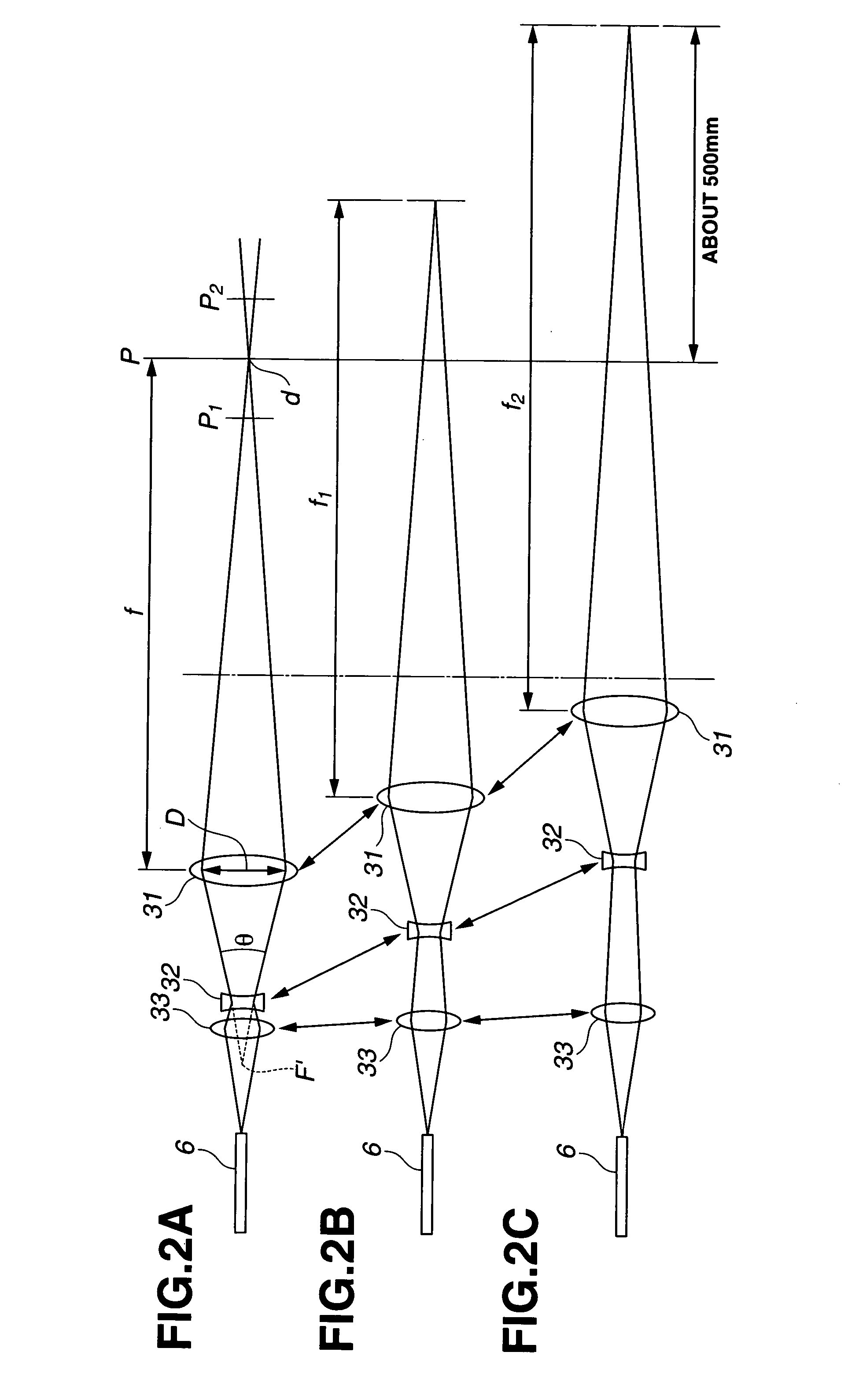
[0026]The following describes a principle for adjusting the laser focal spot size arbitrarily even when the focal length changes according to change in distances among the three lenses. FIGS. 2A through 2C are views showing a principle of adjusting a focal point of a laser beam and the focal spot size of the laser beam in the laser welding apparatus of the

[0027]First lens 31 serves for focusing a laser beam at a focal point. Accordingly, first lens 31 is formed based on a convex lens. In such a convex lens, the focal length changes according to the diffusion angle of the incoming laser beam. The diffusion angle of the laser beam is represented by θ, and defined as an angle at which the laser beam spreads from a virtual focal point indicated by F′ in FIG. 2A, diffused by second lens 32 as mentioned below. The focal length f of first lens 31 decreases with a decrease in diffusion angle θ, i.e. as the laser beam approaches a parallel beam. On the other hand, focal length f increases wi...

second embodiment

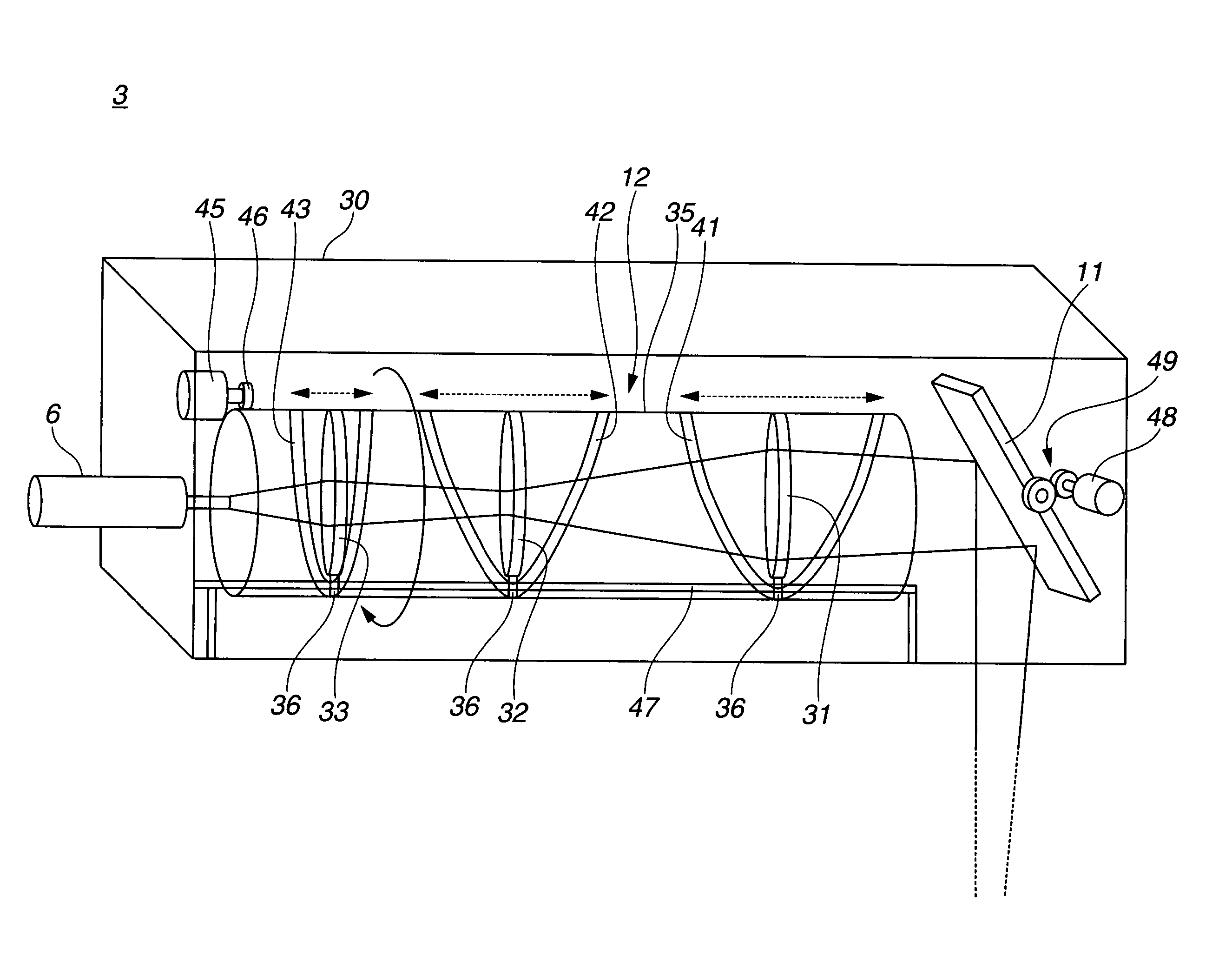
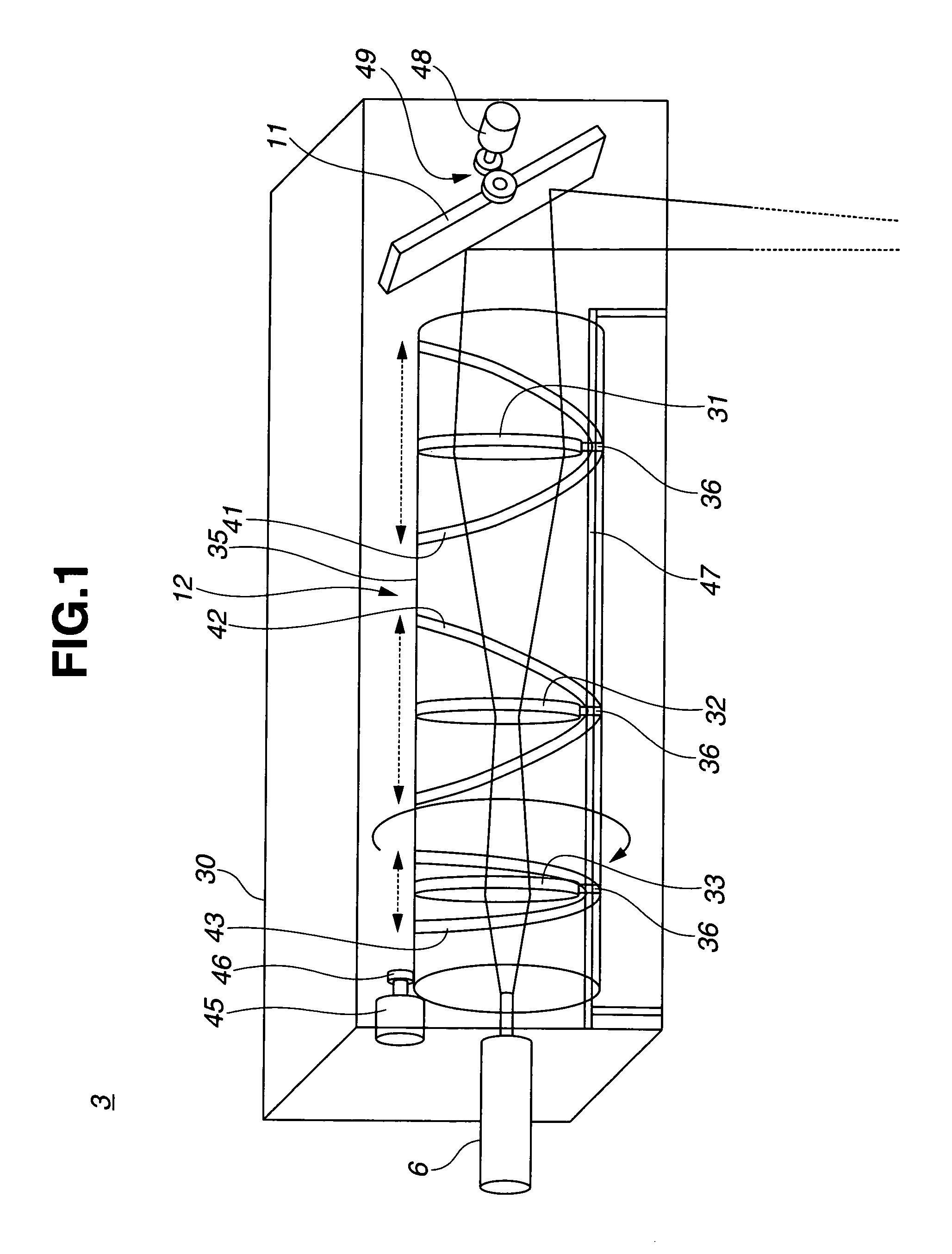
[0039]FIG. 7 is a block diagram showing a control system of the laser welding apparatus of the The laser welding apparatus includes an electrical control unit, i.e. a laser controller 51 for controlling an ON / OFF state of laser oscillator 5, a robot controller 52 for controlling motion of robot 1, and a machining head controller 53 for controlling reflector 11, and motor 45 for actuating lens set 12 or for rotating lens-barrel 35. Controllers 51, 52, and 53 each include an input / output interface (I / O), memories (RAM, ROM), and a microprocessor or a central processing unit (CPU). Laser controller 51 is configured to receive a control signal from robot controller 52, and to control the ON / OFF state of laser oscillator 5, and adjust the intensity of laser beam, in accordance with the control signal. Robot controller 52 is configured to control motion of robot 1, and additionally configured as a main control unit to output a control signal to laser controller 51 to control the ON / OFF s...


PUM

PropertyMeasurementUnit
sizeaaaaaaaaaa
focal lengthaaaaaaaaaa
welding speedaaaaaaaaaa

Abstract

A laser welding apparatus includes a laser welding unit including a first lens adapted to focus a laser beam; a second lens adapted to diffuse the laser beam to the first lens; and a third lens adapted to guide the laser beam to the second lens. The relative positions of the first lens, the second lens, and the third lens, are adjusted to adjust a diffusion angle and a beam width of the laser beam entering the first lens. The laser welding apparatus performs: actuating the laser welding unit to travel at a predetermined speed along a predetermined trajectory; directing the laser beam at a first welding spot; adjusting the focal length to focus the laser beam at the first welding spot; holding the laser focal spot size substantially constant; and directing the laser beam at a second welding spot after completion of welding for the first welding spot.

Description

BACKGROUND OF THE INVENTION[0001]The present invention relates to laser welding apparatus and method.[0002]In recent years, laser welding is increasingly applied to robot welding. A Japanese Patent No. 3229834 shows such a laser welding technique of holding stationary a laser welding device attached to the tip of a robotic arm, and rotating a reflector inside the laser welding device to distribute a laser beam to each of a plurality of welding spots.[0003]There is shown a laser welding technique of adjusting the focal length of a laser beam in accordance with different distances from a laser welding device to a is plurality of welding spots, in the datasheet of “FIBER ELEPHANT,” Number 0002243-01, published by ARGES GmbH, June 2003. If the focal length is adjusted by this laser welding technique, the spot size of the laser beam at focus changes with a change in the focal length. As a result, the amount or density of focused optical energy varies in accordance with the focal length. ...

Claims


Application Information

Patent Timeline
Patent Type & Authority Patents(United States)
IPC IPC(8): G02B7/02B23K26/00
CPCB23K26/046B23K26/0807B23K26/0884B23K26/073B23K26/082G06K19/07732G06K19/04G06F2212/2146
Inventor KAWAI, HITOSHIHAMAGUCHI, YUJISAKURAI, TATSUYA
Owner NISSAN MOTOR CO LTD
Why Eureka
Try Eureka