Localized dynamic light scattering system with doppler velocity measuring capability

a dynamic light scattering and velocity measurement technology, applied in the field of dynamic light scattering, can solve the problems of increasing the overall complexity of the overall process, increasing the overall complexity, and loss of light intensity, and achieves the effect of high sensitivity

Active Publication Date: 2014-08-05
CHOU LIDEK
View PDF2 Cites 3 Cited by
  • Summary
  • Abstract
  • Description
  • Claims
  • Application Information

AI Technical Summary

Benefits of technology

[0009]Therefore, an object of the present invention is to provide a localized dynamic light scattering measurement system that is capable of Doppler velocity or particle size measurements with high sensitivity.

Problems solved by technology

However, accurate measurements of fluid flow velocity are relatively difficult.
However, in order to properly extract the dynamic information, assumption of light undergone a limited number of scattering events needs to be satisfied, meaning that each detected photon has been scattered by the sample under a limited number of scattering.
It would be difficult to accurately interpret the dynamic information of a sample if the degree of multiple scattering is severe enough.
If only a single laser source is utilized for self-mixing, there are multiple beam splitters and multiple pairs of the AOMs 83 required, thereby increasing the overall complexity and loss of light intensity.
In this case, interpretation of the center frequency of the power spectrum is difficult even though the power of the incident beam or the high detection sensitivity of the photodetector 85 is used.

Method used


Image

  • Localized dynamic light scattering system with doppler velocity measuring capability
  • Localized dynamic light scattering system with doppler velocity measuring capability
  • Localized dynamic light scattering system with doppler velocity measuring capability

Examples


Embodiment Construction

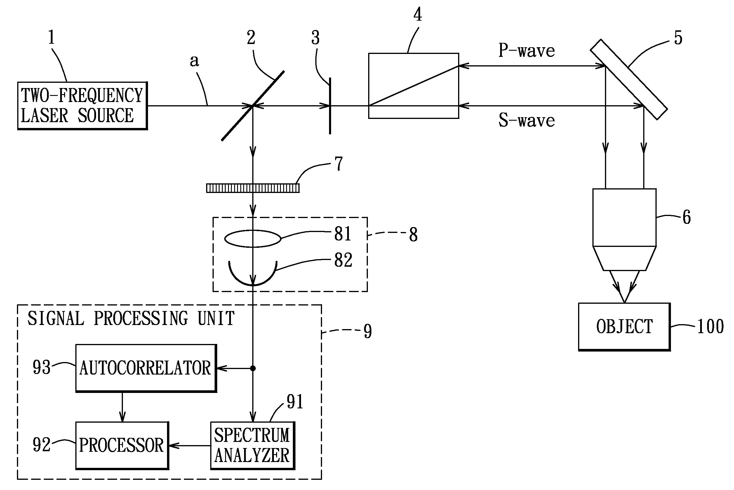
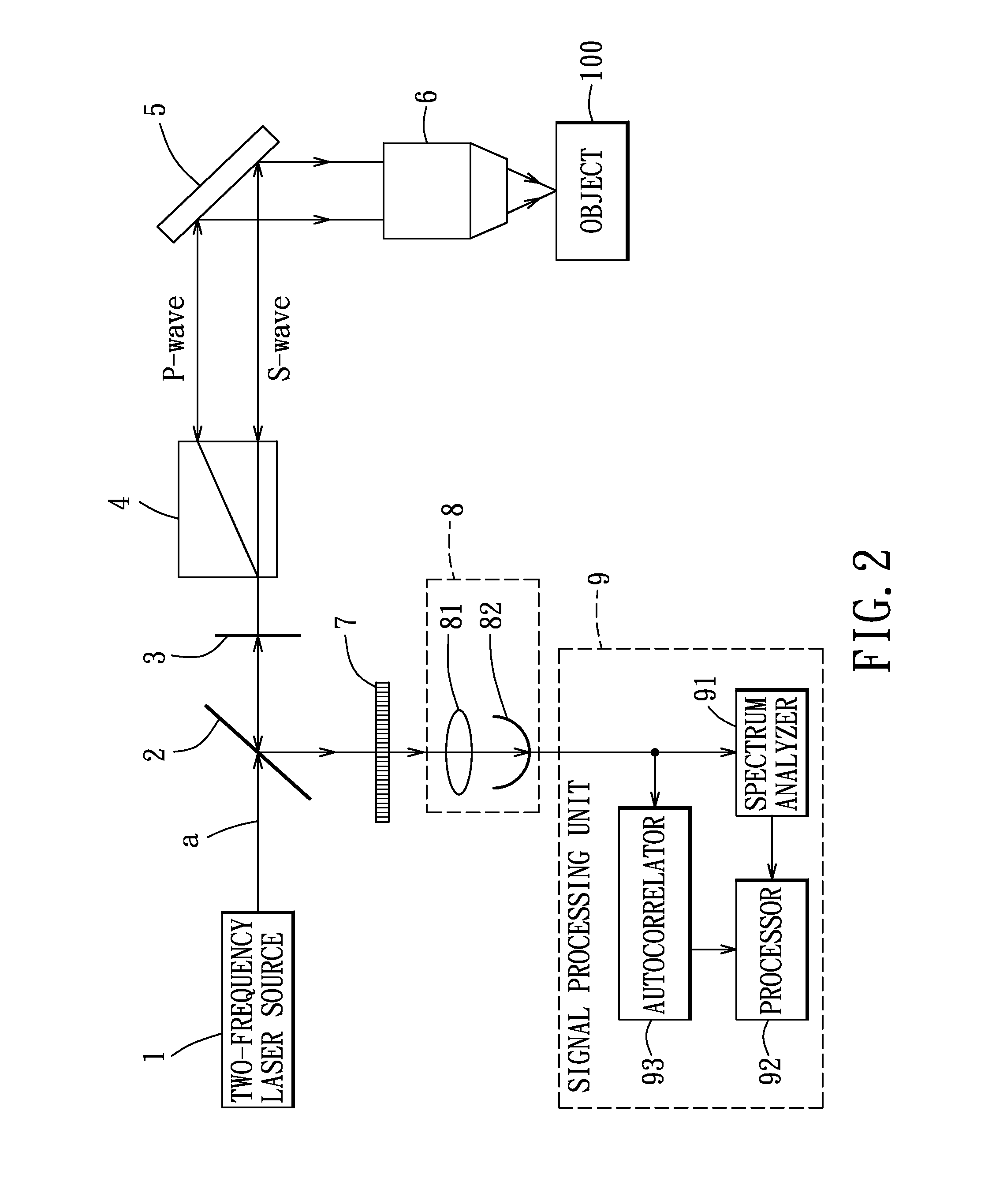
[0030]Referring to FIG. 2, the preferred embodiment of a localized dynamic light scattering measurement system according to the present invention is shown to include a two-frequency laser source 1, a beam splitter 2, an iris 3, a beam displacer 4, a light reflector 5, a focusing lens unit 6, a polarizer 7, a photo detecting unit 8, and a signal processing unit 9.

[0031]The two-frequency laser source 1 produces an input laser beam propagating along an optical axis (a). The input laser beam is composed of orthogonal linearly polarized first and second beam components with slightly different frequencies. In this embodiment, as shown in FIG. 2a, the orthogonal linearly polarized first and second beam components correspond respectively to horizontally polarized and vertically polarized waves, such as P-wave and S-wave in an incident plane, which is defined by a Y-axis and a propagation axis. The propagation axis is oriented at an angle (α) with an X-axis. The angular frequencies of the fi...


PUM

PropertyMeasurementUnit
inner diameteraaaaaaaaaa
flow rateaaaaaaaaaa
flow rateaaaaaaaaaa

Abstract

A localized dynamic light scattering measurement system includes a beam displacer for splitting an incident beam having two orthogonal linearly polarized beam components with slightly different frequencies into two orthogonal linearly polarized output beams focused onto an object to be measured. The beam displacer cooperates with an iris to collect and recombine scattering beams each reversely backscattered at 180 degrees from the object so as to form a signal beam, which is polarized by a polarizer to produce two polarization components, thereby generating a heterodyne interference signal associated with the polarization components. A signal processing unit obtains measurement data on the object based on power spectrum or autocorrelation data corresponding to the heterodyne interference signal.

Description

BACKGROUND OF THE INVENTION[0001]1. Field of the Invention[0002]The invention relates to dynamic light scattering, and more particularly to a localized dynamic light scattering measurement system.[0003]2. Description of the Related Art[0004]Laser Doppler velocimetry (LDV) is a well known technique for contactless measurement of the speed and direction of an object in motion, as well as the flow velocity of liquid materials. The motion of a solid object is easy to detect and measure. However, accurate measurements of fluid flow velocity are relatively difficult. Similar to an LDV system, which is used to detect and measure velocity of motions, a dynamic light scattering (DLS) system is also used to characterize motion of particles. But unlike in an LDV system, in which the signal measured is deterministic, the light scattering signal in DLS is a stochastic process that can only be described statistically. Based on detection and measurement of single Rayleigh scattered light from an e...

Claims


Application Information

Patent Timeline
Patent Type & Authority Patents(United States)
IPC IPC(8): G01N15/02G01N21/49G01P3/36
CPCG01N21/49G01P3/36G01N15/0211G01P3/366G01S7/4816G01S7/493G01N2015/0038G01S17/58G01N2015/0222G01S7/4911G01S7/499G01S7/4812G01S7/4917
Inventor CHOU, LIDEK
Owner CHOU LIDEK
Why Eureka
Try Eureka