
Radio transmission system and electronic device
a transmission system and electronic device technology, applied in electromagnetic wave modulation, multi-frequency-changing modulation transference, instruments, etc., can solve the problems of limited transmission speed and transmission capacity of signal transmission by electric wiring, increase in power consumption, and limited transmission speed and transmission capacity. , to achieve the effect of simple and inexpensive constitution
- Summary
- Abstract
- Description
- Claims
- Application Information
AI Technical Summary
Benefits of technology
Problems solved by technology
Method used
Image

Examples
first embodiment
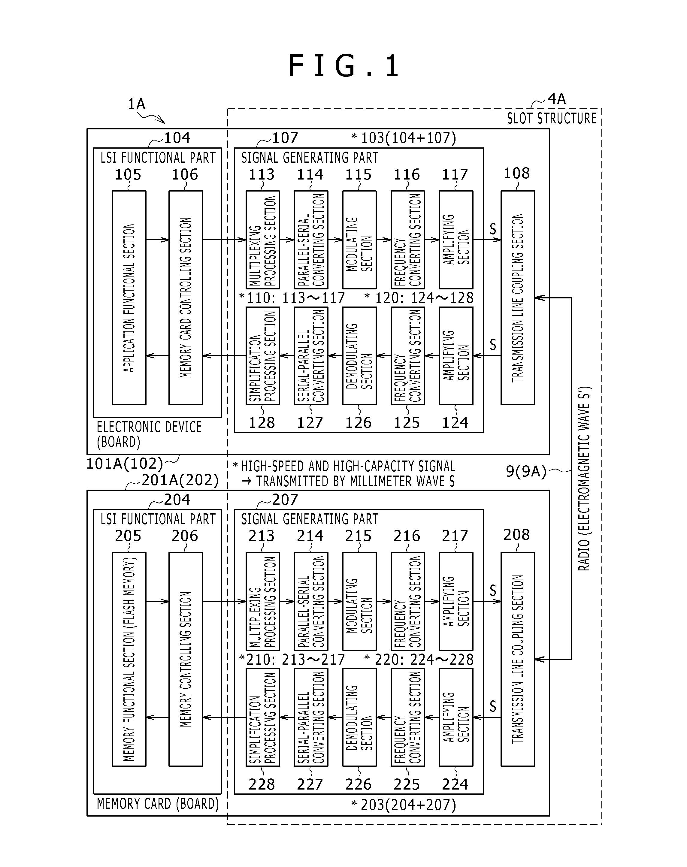
[0130]As shown in FIG. 1, the slot structure 4A according to the first embodiment contributes to the signal generating part 107 and the transmission line coupling section 108 on the electronic device 101A side, the signal generating part 207 and the transmission line coupling section 208 on the memory card 201A side, and the millimeter wave signal transmission line 9 (dielectric transmission line 9A). The dielectric transmission line 9A is provided between the transmission line coupling section 108 and the transmission line coupling section 208.
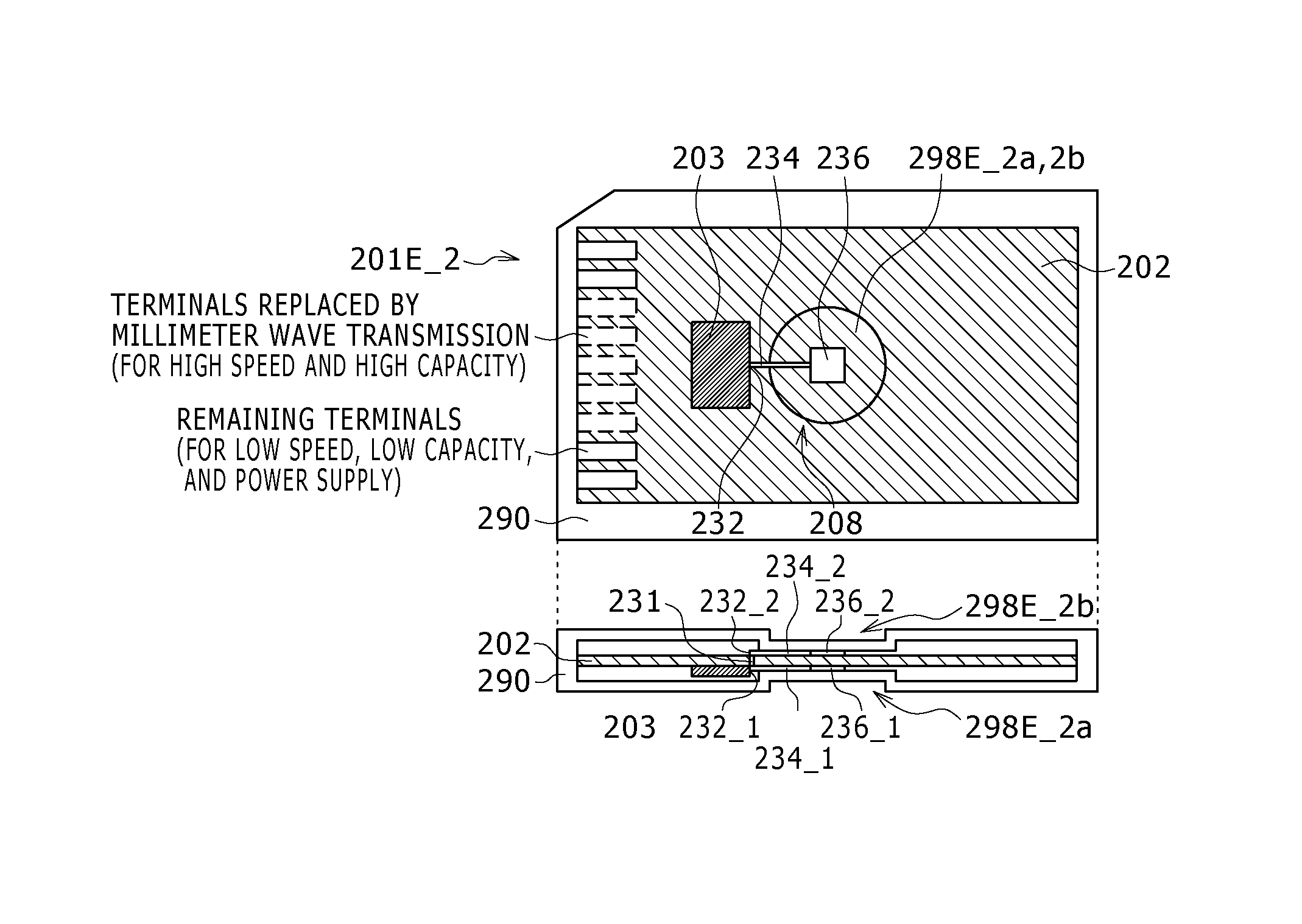
[0131]Incidentally, unlike a signal interface using related-art electric wiring, the present embodiment flexibly provides for a high-speed characteristic and high capacity by performing signal transmission in the millimeter wave band as described above. For example, in the first embodiment, only signals desired to have a high-speed characteristic and a high-capacity characteristic are set as objects for communication in the millimeter wave ba...
second embodiment
[0168]FIG. 5 is a diagram of assistance in explaining a signal interface in a radio transmission system according to a second embodiment. FIG. 5 is a diagram of assistance in explaining the signal interface in the radio transmission system 1B according to the second embodiment from an aspect of functional configuration.
[0169]The second embodiment makes a millimeter wave signal transmission line 9 a substantial free space. The “substantial free space” means that while the casings of an electronic device 101B and a memory card 201B are a dielectric, a millimeter wave signal is transmitted between the electronic device 101B and the memory card 201B via a transmission line of a free space (free space transmission line 9B) ignoring the dielectric parts.
[0170]In terms of functional configuration, only the dielectric transmission line 9A according to the first embodiment is replaced with the free space transmission line 9B, and the second embodiment is similar to the first embodiment in ot...
third embodiment
[0172]FIG. 6 is a diagram of assistance in explaining a signal interface in a radio transmission system according to a third embodiment. FIG. 6 is a diagram of assistance in explaining the signal interface in the radio transmission system 1C according to the third embodiment from an aspect of functional configuration.
[0173]The third embodiment applies both the dielectric transmission line 9A according to the first embodiment and the free space transmission line 9B according to the second embodiment as the millimeter wave signal transmission line 9. In terms of functional configuration, the third embodiment is a mere combination of the first embodiment and the second embodiment. Therefore description of other parts will be omitted.
[0174]The mechanism of the third embodiment has two systems as millimeter wave signal transmission line 9, and the concept also corresponds to an example of “space division multiplexing” in a fifth embodiment to be described later. While one system of the d...
PUM
 Abstract
Description
Claims
Application Information