Controllable buoyant system and method

a technology of buoyant system and controllable buoy, which is applied in the direction of position/direction control, balloon aircraft, aircraft floors, etc., can solve the problems of not being able to adjust the pressure valve according to different ambient conditions, not being able to achieve sufficient accuracy, and not being able to maintain a constant height. , to achieve the effect of better control

Inactive Publication Date: 2014-08-26
NEW CREATE LTD
View PDF21 Cites 47 Cited by
  • Summary
  • Abstract
  • Description
  • Claims
  • Application Information

AI Technical Summary

Benefits of technology

[0016]It is an object of the present invention to provide a buoyant support structure having a controller for controlling the height of the support structure that does not require an anchoring point connected to ground or calibration for each object attached thereto and that provides better control than the approaches proposed in WO 07 / 036930.
[0018]a support structure having a sealed hollow enclosure for containing a first gas and being surrounded by a second gas such that either the first gas or the second gas is lighter than ambient air, said hollow enclosure being pre-filled with said first gas via a one-way valve that prevents the first gas from escaping from the hollow enclosure,
[0024]In some embodiments, a controlled change in density of the first gas in the hollow chamber serves to adjust the buoyancy of the support structure.

Problems solved by technology

While such approaches work when conditions are clearly defined and not subject to constant fluctuation, they are not suited for maintaining a constant height when ambient conditions vary.
Moreover, the need to calibrate the pressure valve according to different ambient conditions and objects may not be convenient or may not be possible with sufficient accuracy.
However, it is not acceptable where servo-assisted altitude regulation is required because once the helium is released in order to reduce buoyancy there is no way that the buoyancy can be subsequently raised since the quantity of helium cannot be increased.
This is an inherent problem with using the helium to regulate the buoyancy as distinct from merely providing the buoyancy.
Furthermore, the need to carry a gas cylinder is not practical for portable devices where the mass of the gas cylinder may well exceed that of the rest of the system.
The controller allows equilibrium to be maintained once the airship has reached a required height under manual control of a pilot, but it is not capable of automatically raising the airship accurately to a required height.
It is clear that while such an approach may be feasible for an airship where differential pressure over an extended height range may be measurable, it is not feasible for use at limited height ranges where pressure gradients are negligible.
Thus, while pressure gradient between sea level and 1 km is significant, the pressure difference over a height difference of 5 m is a mere 72 Pa, which is probably too low to serve as a practical error signal for a servo control system.
Certainly, the difference in atmospheric pressure at 3 m (101,282 Pa) and 3.5 m (101,274 Pa) is a mere 8 Pa and it is clear that this cannot serve as a practical feedback signal.
Likewise, once the airship has reached a target altitude, to maintain it at this altitude to within a resolution of ±1 m based on differential pressure feedback is inconceivable.
Furthermore, controlling height based on pressure variations allows height to be maintained relative to sea level, but it does not accommodate variations is terrain.
But it is not suitable for accurate height control relative to ground.

Method used


Image

  • Controllable buoyant system and method
  • Controllable buoyant system and method
  • Controllable buoyant system and method

Examples


Embodiment Construction

[0037]In the following description, features that appear in more than one drawing will be identified by identical reference numerals.

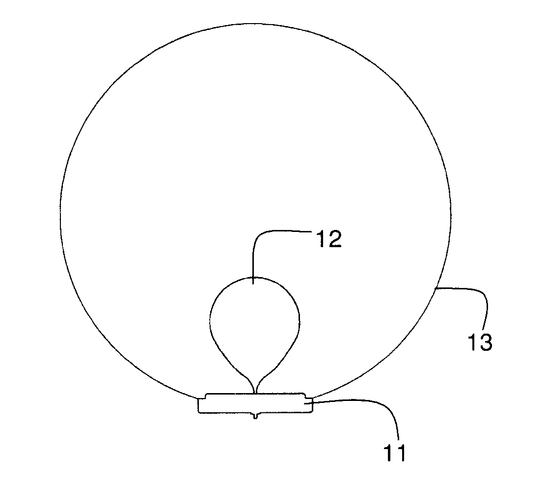
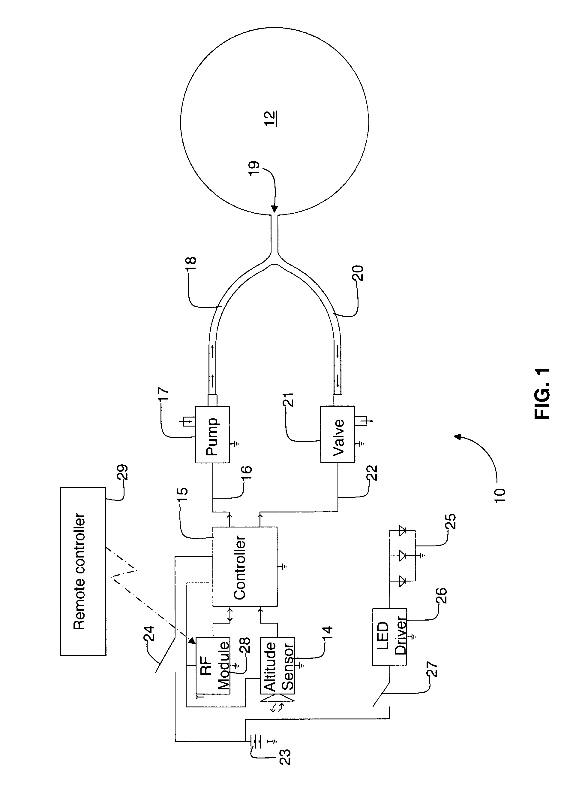
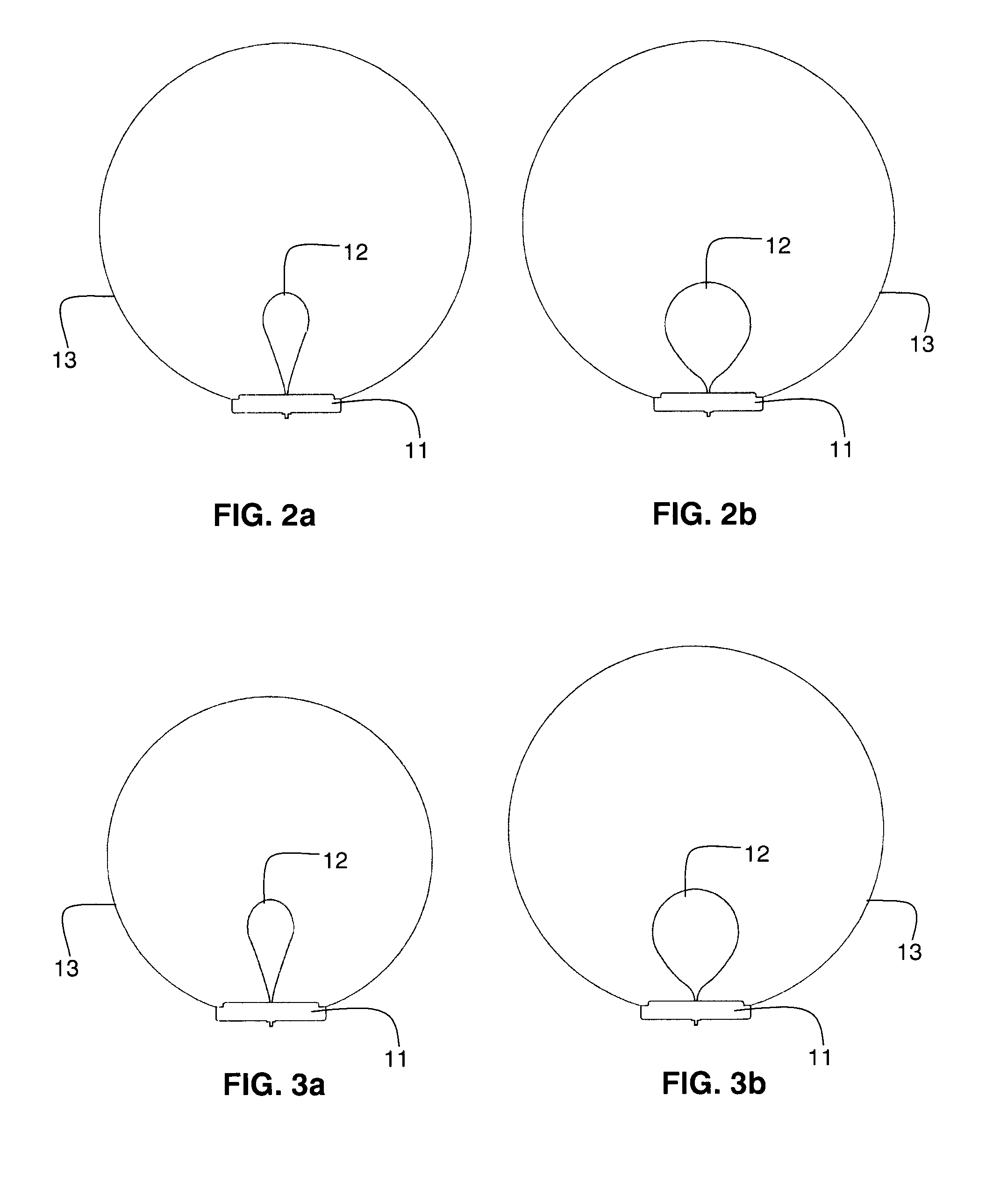
[0038]FIG. 1 shows functionally a control system 10 according to a first embodiment for regulating the height in space of a support structure 11 shown schematically in FIGS. 2a and 2b. The support structure 11 includes a flexible balloon 12 (constituting a hollow enclosure) that is sealingly supported inside an outer enclosure 13 (shown in FIGS. 2a and 2b). The balloon 12 contains an adjustable volume of a first gas that is surrounded by a different second gas in the outer enclosure. Typically the first gas in the balloon 12 is air and the second gas in the outer enclosure 13 is helium. An altitude sensor 14 is mounted in association with the support structure 11 for generating an altitude signal that is a function of an altitude of the support structure, and a controller 15 is coupled to the altitude sensor 14 and is responsive to the altitude signal ...


PUM


Abstract

A controllable buoyant system (10) includes a support structure having a sealed hollow enclosure (12) containing a first gas and surrounded by a second gas, either the first gas or the second gas being lighter than ambient air. The hollow enclosure is pre-filled with the first gas via a one-way valve that prevents the first gas escaping and an altitude sensor (14) generates an altitude signal indicative of a height of the support structure. A height transducer (17, 21, 61, 66, 67, 68) coupled to the hollow enclosure is responsive to the altitude signal for varying the buoyancy of the support structure. A controller (15) is coupled to the altitude sensor and to the height transducer and is responsive to the altitude signal and to at least one reference altitude signal for automatically controlling the height transducer in order to maintain the support structure buoyant at the preset altitude.

Description

FIELD OF THE INVENTION[0001]This invention relates to a controllable buoyant system for anchoring objects in space without requiring an anchoring point connected to ground.BACKGROUND OF THE INVENTION[0002]WO 07 / 036930 in the name of the present applicant describes an object adapted to float in air when filled with a gas having lower specific gravity than air, the object including a hollow enclosure having an inlet coupled to a pressure adjustment means for regulating pressure of gas within the enclosure so as to ensure that a buoyancy force alone of the enclosure counteracts a weight of the object. A number of general approaches for regulating gas pressure within the enclosure are suggested. Thus, in accordance with one approach the enclosure is part of a buoyant platform, which supports an object in space and it is suggested to couple a gas connector to an inlet of the enclosure via an adjustable pressure valve, whereby gas may be fed at a controlled pressure to the buoyant platfor...

Claims


Application Information

Patent Timeline
Patent Type & Authority Patents(United States)
IPC IPC(8): B64B1/44B64B1/64B64B1/58B64B1/62A63H27/10F21V3/02
CPCA63H27/10F21V3/026B64B1/62B64B1/44A63H2027/1066
Inventor SHENHAR, OZ
Owner NEW CREATE LTD
Why Eureka
Try Eureka