Digital microfluidics system with disposable cartridges

a microfluidics and cartridge technology, applied in the direction of fluid pressure measurement, liquid/fluent solid measurement, peptide measurement, etc., can solve the problem of large-scale systems that are not designed to be portabl

Active Publication Date: 2014-09-02
TECAN TRADING AG
View PDF21 Cites 21 Cited by
  • Summary
  • Abstract
  • Description
  • Claims
  • Application Information

AI Technical Summary

Benefits of technology

[0028]Not connecting the electrically conductive material of the cover plate with a source of a certain electrical potential during manipulating samples in liquid droplets enables more simple construction of a movable or fixed top plate.
[0029]The conductive layer preferably is removed from the cartridge's top film or top layer respectively. Thus, without having any conductive layers that would contribute to electrowetting movements of the liquid droplets manipulated, the self-contained disposable cartridge according to the invention can be of very simple and low-cost construction.

Problems solved by technology

They are also larger systems that are not designed to be portable.

Method used


Image

  • Digital microfluidics system with disposable cartridges
  • Digital microfluidics system with disposable cartridges
  • Digital microfluidics system with disposable cartridges

Examples


first embodiment

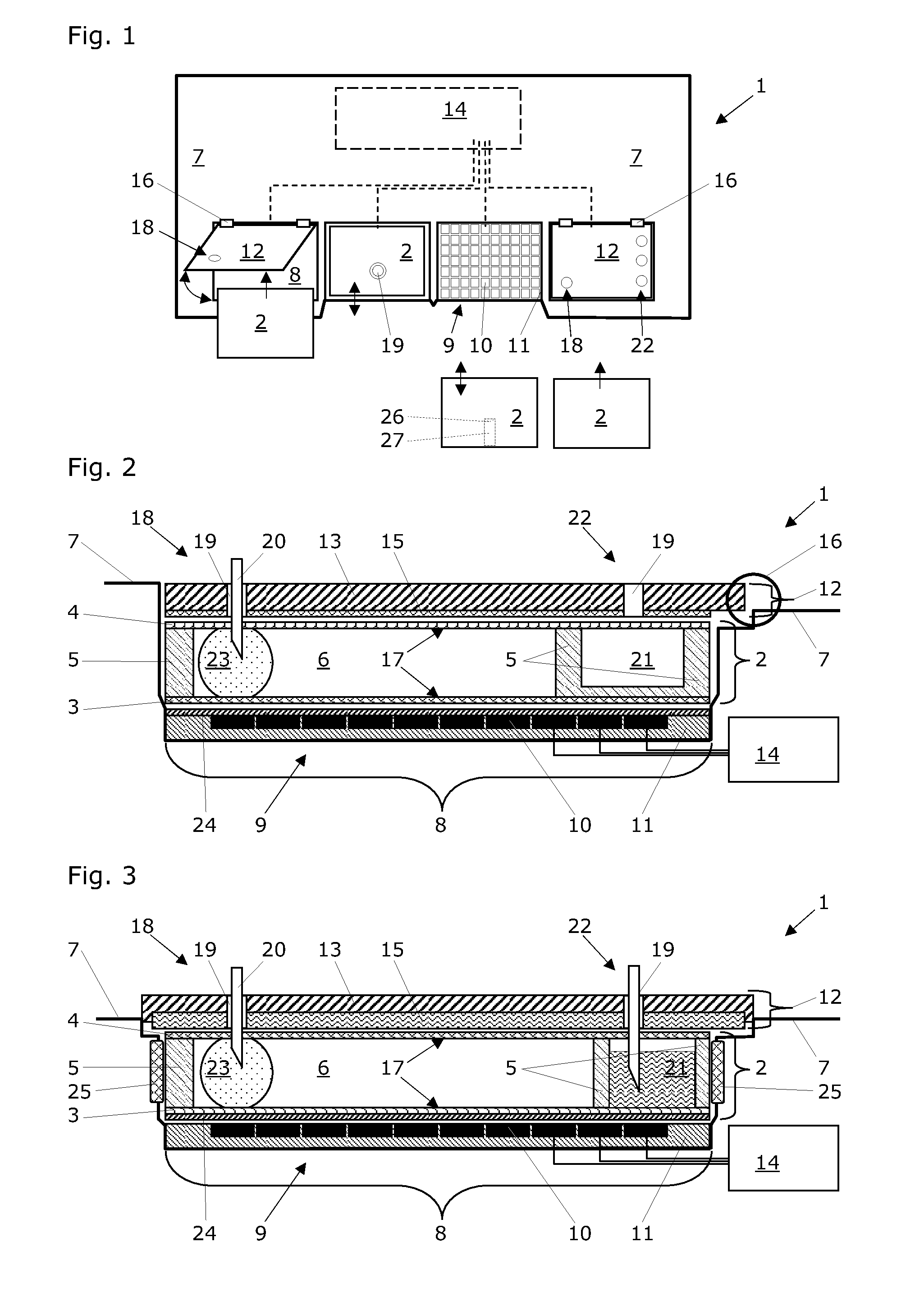
[0053]The FIG. 2 shows a section view of one exemplary cartridge accommodation site 8 with a disposable cartridge 2 accommodated therein. The cover plate 12 is mechanically connected with the base unit 7 of the digital microfluidics system 1 via a hinge 16; thus, the cover plate 12 can swing open and a disposable cartridge 2 can be placed on the cartridge accommodation site 8 via top-entry loading (see FIG. 1). The electrically conductive material 15 of the cover plate 12 is configured as a thin metal plate or metal foil that is attached to the top substrate 13.

[0054]Alternatively, the electrically conductive material 15 of the cover plate 12 is configured as a metal layer that is deposited onto the top substrate 13. Such deposition of the conductive material 15 may be carried out by chemical or physical vapor deposition techniques as they are known per se.

[0055]The cover plate 12 is configured to apply a force to a disposable cartridge 2 that is accommodated at the cartridge accom...

second embodiment

[0058]The FIG. 3 shows a section view of one exemplary cartridge accommodation site 8 with a disposable cartridge 2 accommodated therein. Different to the previous embodiment, the cover plate 12 is mechanically connected with the base unit 7 of the digital microfluidics system 1 and immovably fixed therewith. The electrically conductive material 15 of the cover plate 12 is configured as a thick metal plate that is attached to the top substrate 13. Here, the cover plate 12 is not configured to apply a force to the disposable cartridge 2 that is accommodated at the cartridge accommodation site 8 of the base unit 7; thus, the cover plate 12 stays in place and a disposable cartridge 2 can be placed on the cartridge accommodation site 8 via front-entry loading. Such front-entry loading usually includes a movement of the disposable cartridge 2 in a direction that is parallel to the electrode array 9 (see FIG. 1). In order to enable proper drawing-in of the disposable cartridge 2 and to n...

third embodiment

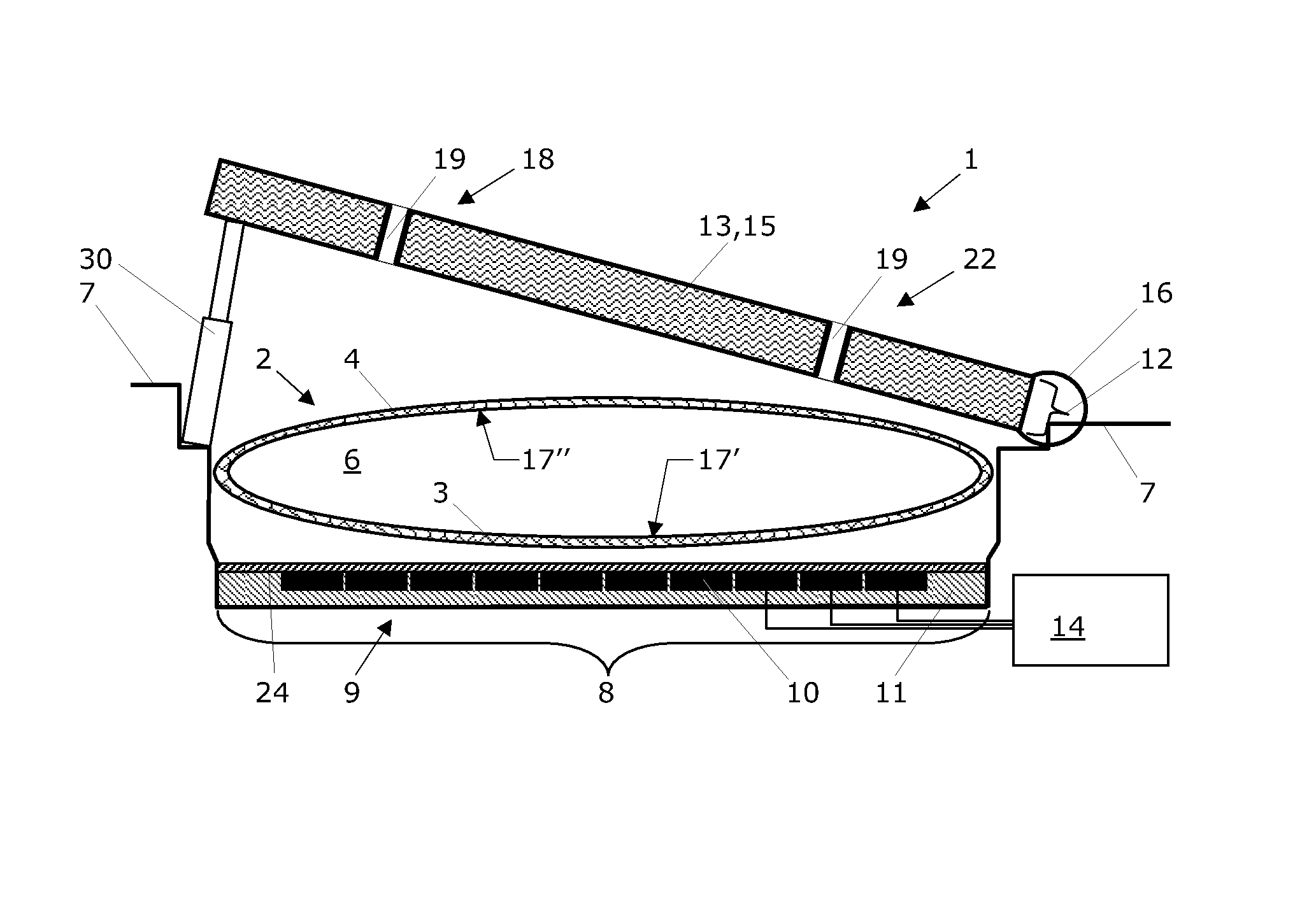
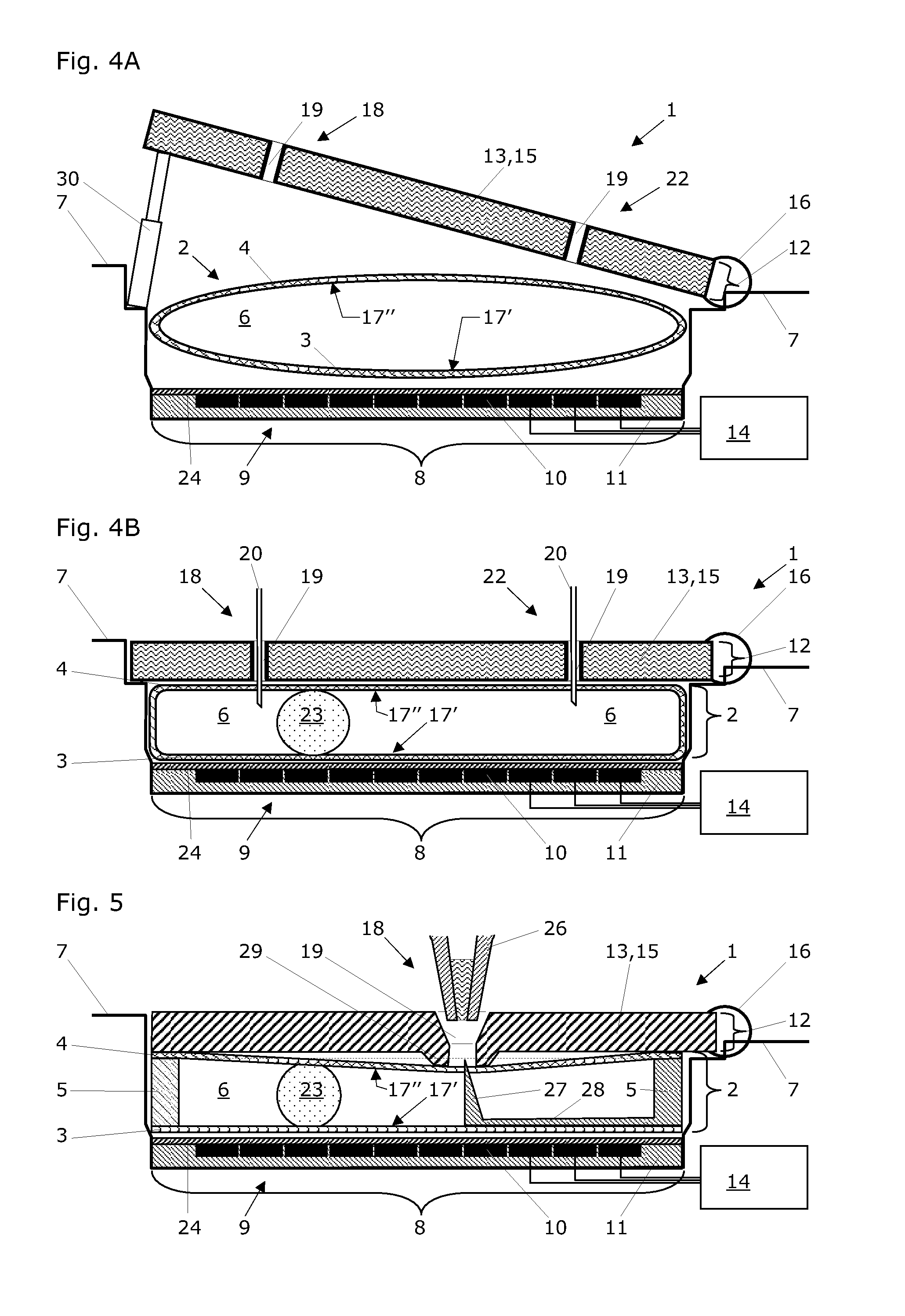
[0062]The FIG. 4 shows section views of one exemplary cartridge accommodation site 8 with a disposable cartridge 2 accommodated therein. The electrode array 9 is fixed to a bottom substrate 11 and every individual electrode 10 is electrically and operationally connected with the central control unit 14 (only three connections of the ten electrodes 10 are drawn here). The digital microfluidics system 1 is configured for manipulating samples in liquid droplets 23 within disposable cartridges 2 that contain a gap 6. Accordingly, the samples in liquid droplets 23 are manipulated in the gap 6 of the disposable cartridge 2.

[0063]The cover plate 12 is mechanically connected with the base unit 7 of the digital microfluidics system 1 via a hinge 16; thus, the cover plate 12 can swing open and a disposable cartridge 2 can be placed on the cartridge accommodation site 8 via top-entry loading (see FIG. 1). Here, the electrically conductive material 15 of the cover plate 12 is made of metallic ...


PUM

PropertyMeasurementUnit
sizeaaaaaaaaaa
gap widthaaaaaaaaaa
electrical potentialaaaaaaaaaa

Abstract

A digital microfluidics system manipulates samples in liquid droplets within disposable cartridges and has disposable cartridges each with a bottom layer, a top layer and a gap therebetween. A base unit with cartridge accommodation sites and at least one electrode array with electrodes works with a cover plate at the sites and a control unit for controlling selection of the electrodes and for providing them with voltage pulses for manipulating liquid droplets within the cartridges by electrowetting. The cover plate has an electrically conductive material that extends parallel to the array. A selection of disposable cartridges and a method for manipulating samples in liquid droplets that adhere to a hydrophobic surface can be used with the system.

Description

FIELD OF TECHNOLOGY[0001]The present invention relates to a digital microfluidics system or device into which one or more disposable cartridges for manipulating samples in liquid droplets therein can be inserted. The digital microfluidics system comprises an electrode array supported by a substrate, and a central control unit for controlling the selection of individual electrodes of this electrode array and for providing them with individual voltage pulses for manipulating liquid droplets by electrowetting. Thus, the invention also relates to droplet actuator devices for facilitating droplet actuated molecular techniques.RELATED PRIOR ART[0002]Automated liquid handling systems are generally well known in the art. An example is the Freedom EVO® robotic workstation from the present applicant (Tecan Schweiz AG, Seestrasse 103, CH-8708 Männedorf, Switzerland). This device enables automated liquid handling in a stand-alone instrument or in automated connection with an analytical system. ...

Claims


Application Information

Patent Timeline
Patent Type & Authority Patents(United States)
IPC IPC(8): G01N27/00
CPCB01L3/502792B01L3/502715B01L3/505B01L2200/027B01L2200/0673B01L2300/043B01L2300/044B01L2300/089B01L2300/123B01L2400/0427
Inventor BJORNSON, TORLEIF OVEFEIGLIN, MARC NATHANFRANKLIN, MICHAEL BENJAMINKOPF-SILL, ANNE R.LEE, TRAVISWANG, KAILIANG
Owner TECAN TRADING AG
Why Eureka
Try Eureka