Interferece-fit stop collar and method of positioning a device on a tubular

a technology of interfering fit and stop collar, which is applied in the direction of hose connection, coupling, borehole/well accessories, etc., can solve the problems of insufficient load capacity of tubulars, insufficient holding force and insufficient grip of conventional stop collars. , to achieve the effect of increasing the grip area and the resulting holding force of stop collars, reducing the cost of manufacturing stop collar components, and increasing the extension of fingers from the bas

Active Publication Date: 2014-09-16
INNOVEX DOWNHOLE SOLUTIONS INC
View PDF42 Cites 25 Cited by
  • Summary
  • Abstract
  • Description
  • Claims
  • Application Information

AI Technical Summary

Benefits of technology

The invention relates to a method of installing a stop collar on a tubular for load capacity purposes. The method provides a superior load capacity compared to conventional stop collars and grips the tubular without causing any damage to its exterior. The large grip area and uniform grip pressure across the grip area contribute to the excellent load capacity with minimal impact on the effective P.O.D. The method includes steps of applying an uncured epoxy adhesive to certain components of the stop collar to facilitate installation and enhance the grip of the collar on the tubular. The epoxy acts as a lubricant during installation and cures to bond the collar to the tubular for improved load capacity. Additionally, the method may include steps of applying an uncured epoxy to the tubular and / or to the interior curved surfaces of the collar to promote bonding.

Problems solved by technology

Conventional stop collars may be too large in outer diameter for certain applications.
Additionally, conventional stop collars may not provide sufficient holding force without damaging the tubular.
Set screw-type stop collars rely on highly localized contact with the tubular and typically do not provide adequate load capacity on tubulars of hardened materials, such as high-carbon steel or other extremely hard alloys, because the set screw does not sufficiently penetrate the surface of the hardened tubular.
Even a set screw-type stop collar having multiple set screws “bites” into only a small cumulative area on the tubular, and the load capacity is limited, especially on hardened tubulars.
When the load capacity of a set screw-type stop collar is exceeded, the set screws may slip and cause scratching and scoring of the tubular, thereby damaging any protective coatings and / or possibly creating corrosion initiation sites.
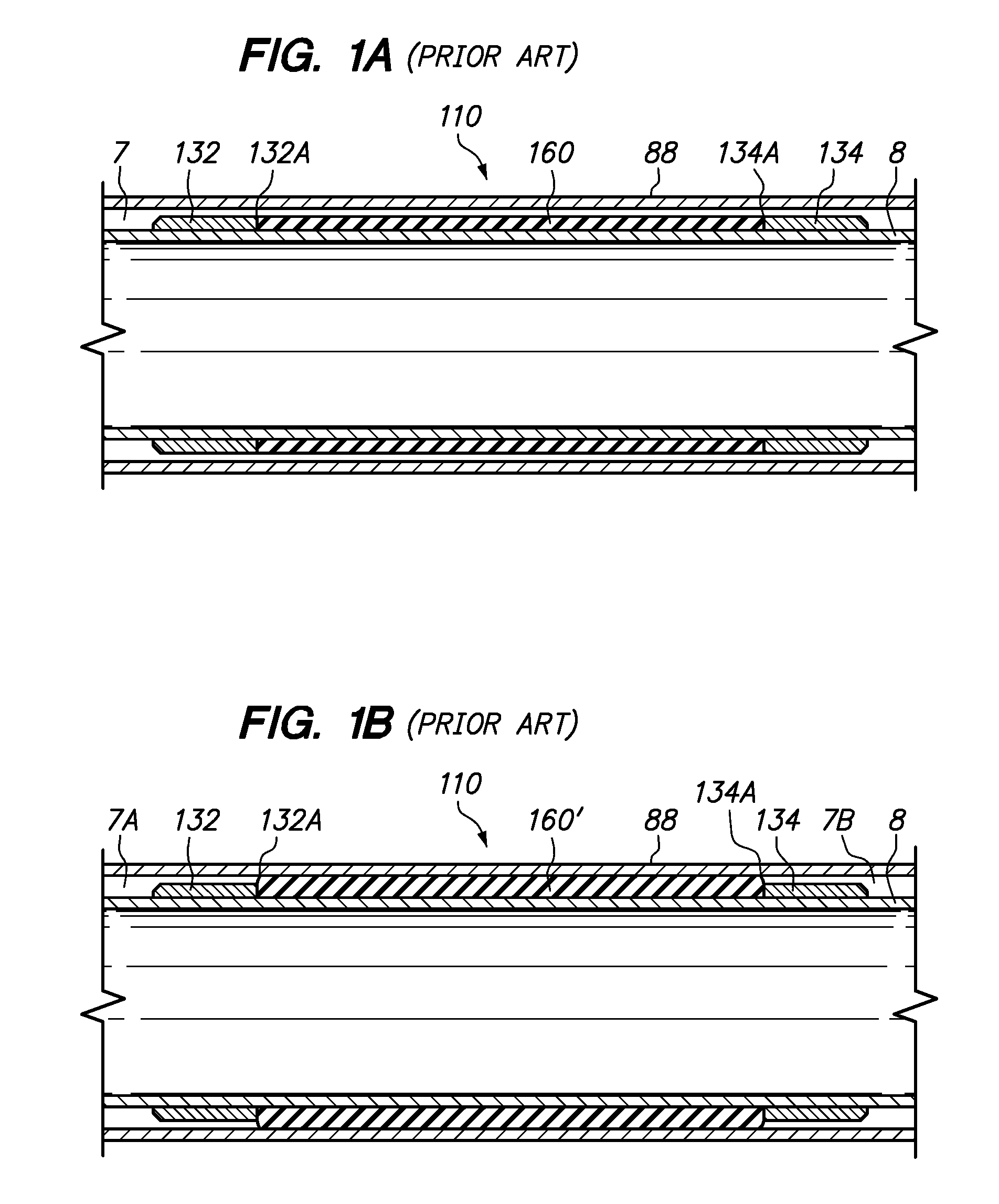
A shortcoming of crimped stop collars is that they generally require deformation of the wall of the tubular 8 (or the mandrel) on which the stop collar is installed in order to provide sufficient load capacity, and deformation of the tubular (or the mandrel) may be impractical or undesirable.
Also, crimping a collar onto a tubular may require a heavy machine to generate the forces required to deform the collar and / or the tubular, and this requirement may prohibit field installation.
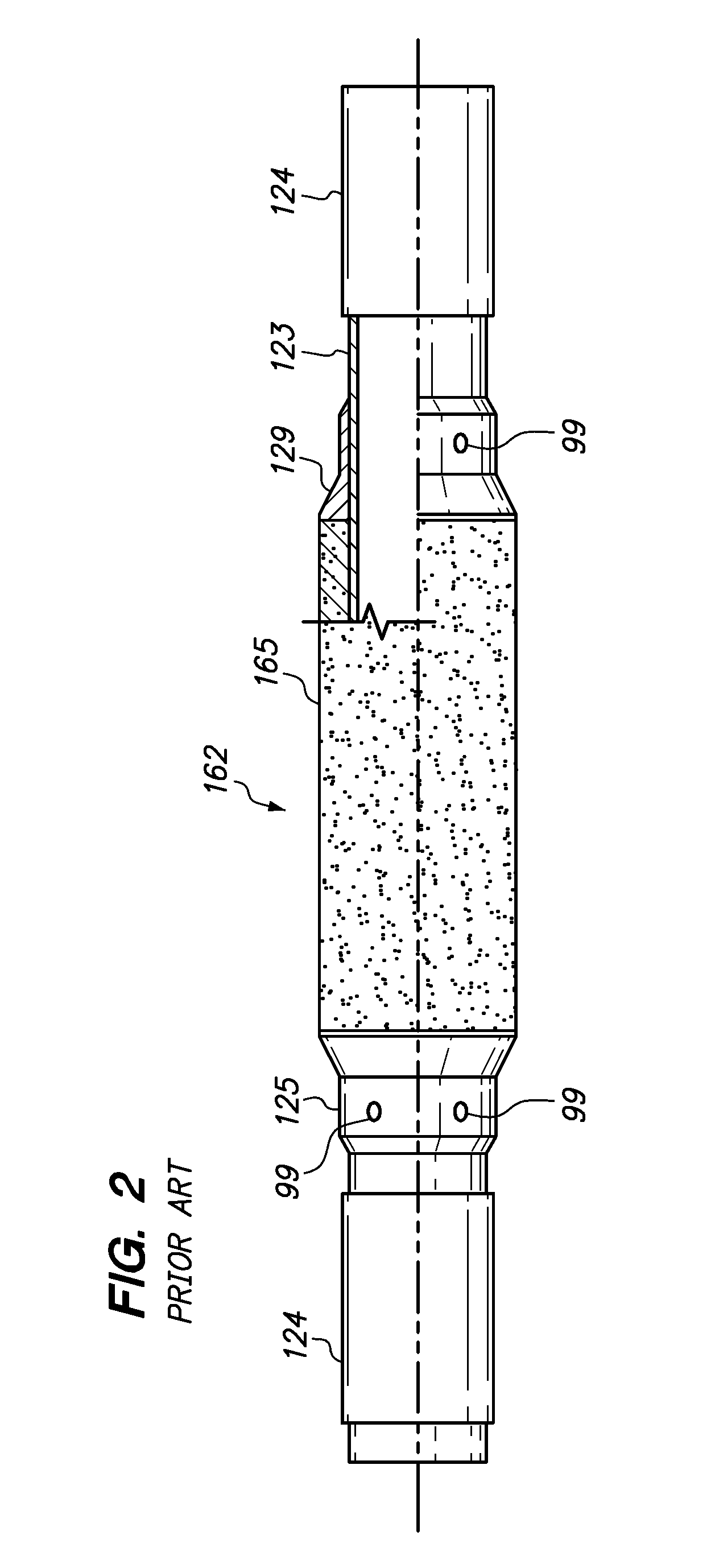
A shortcoming of a sub-mounted packer (see FIG. 2) is that the packer must be positioned at a threaded connection within a tubular string, and it cannot be conveniently disposed at any location along any tubular segment.
Adhesively-secured stop collars, like set-screw type stop collars, may lack sufficient load capacity required to, for example, push or pull a centralizer through a tight restriction.
Adhesively-secured stop collars may also require a period of inactivity after application for the adhesive to cure enough for the stop collar to bear a load.
A stop collar comprising a plastic compound molded onto the tubular may chip or shatter from impact with bore restrictions, and a piece of the stop collar may break off and become lodged in a critical piece of equipment, such as a BOP or valve, or it may otherwise impair movement of the tubular within a the bore.

Method used


Image

  • Interferece-fit stop collar and method of positioning a device on a tubular
  • Interferece-fit stop collar and method of positioning a device on a tubular
  • Interferece-fit stop collar and method of positioning a device on a tubular

Examples


Embodiment Construction

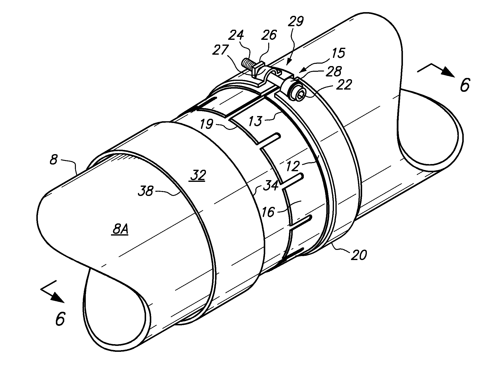
[0077]FIG. 3 is a perspective view of a base 12 (e.g., tubular base) that may be used to form one embodiment of a stop collar, the base 12 having a bore to receive a tubular 8 and a set of fingers 16 extending from the base 12. The depicted fingers 16 of the base 12 extend in a first direction along the exterior 8A of the tubular 8, and the depicted fingers 16 are angularly distributed about the base 12 and separate by a plurality of slots 17. Base 12 may comprise a gap 15 to allow variation of the diameter of the bore of the base 12, e.g., by elastic deformation of the base 12 to close or open the gap 15. Base 12 may comprise a stop wall 13 to limit the extent to which a sleeve may be received onto the fingers 16. Fingers 16 may be coextensive, e.g., in axial length of extension from the base 12. Fingers 16 may comprise a taper (not shown) along their length or along a portion the length of extension from the base 12, and / or the fingers 16 may comprise a bevel 19 to engage and guid...


PUM


Abstract

A stop collar is assembled using a method including the steps of receiving a bore of a base having a set of fingers extending along an exterior of a tubular, receiving a bore of a sleeve onto the tubular adjacent the set of fingers, and receiving the sleeve onto the set of fingers in an interference-fit. In alternate embodiments, the base comprises a plurality of angularly distributed fingers and / or the base comprises a gap to permit conformance of the base to the tubular. A fingerless base may cooperate with one or more separate fingers to form a base. In an embodiment of the method, the sleeve may be thermally expanded prior to the step of receiving the sleeve onto the set of fingers. The sleeve may be heated to expand the bore prior to being received onto the set of fingers.

Description

STATEMENT OF RELATED APPLICATIONS[0001]This application claims the benefit of U.S. Provisional Application No. 61 / 287,665 filed on Dec. 17, 2009, U.S. Provisional Application No. 61 / 237,202 filed on Aug. 26, 2009, and U.S. Provisional Application No. 61 / 221,716 filed on Jun. 30, 2009, and is a continuation-in-part of U.S. application Ser. No. 12 / 756,173 filed on Apr. 7, 2010, which claims the benefit of U.S. Provisional Application No. 61 / 287,665 filed on Dec. 17, 2009, U.S. Provisional Application No. 61 / 237,202 filed on Aug. 26, 2009, U.S. Provisional Application No. 61 / 221,716 filed on Jun. 30, 2009, and U.S. Provisional Application No. 61 / 167,482 filed on Apr. 7, 2009, and is also a continuation-in-part of U.S. application Ser. No. 12 / 755,981 filed on Apr. 7, 2010, which claims the benefit of U.S. Provisional Application No. 61 / 287,665 filed on Dec. 17, 2009, U.S. Provisional Application No. 61 / 237,202 filed on Aug. 26, 2009, U.S. Provisional Application No. 61 / 221,716 filed on ...

Claims


Application Information

Patent Timeline
Patent Type & Authority Patents(United States)
IPC IPC(8): E21B19/00B25B27/10E21B17/00E21B19/16F16D1/08
CPCE21B19/16F16D1/0858E21B17/00B25B27/10E21B17/006Y10T24/1457Y10T29/53987Y10T403/69
Inventor BUYTAERT, JEANMILLER, EUGENE EDWARDHINING, IRA EUGENE
Owner INNOVEX DOWNHOLE SOLUTIONS INC
Why Eureka
Try Eureka