Continuous tension, discontinuous compression systems and methods

a compression system and discontinuous technology, applied in the direction of buildings, constructions, buildings, etc., can solve the problems of reducing the slenderness ratio, significantly less flexibility, and substantial gaps between adjacent panels and between panels and compression members, so as to improve the volume-to-weight and volume-to-surface ratios

Active Publication Date: 2014-09-16
NADEAU GERARD F
View PDF18 Cites 12 Cited by
  • Summary
  • Abstract
  • Description
  • Claims
  • Application Information

AI Technical Summary

Benefits of technology

[0014]With a knowledge of the state of the art as summarized above, the present inventor set forth with the basic object of devising of tensegrity structures and methods for exploiting the same that exhibit desirable structural integrity while providing for efficiency in the use of material and enclosure of space while providing opportunities for improved volume-to-weight and volume-to-surface ratios.
[0015]A further object of embodiments of the invention is to provide tensegrity structures that can pursue widely variable shapes and sizes.
[0027]In such embodiments, the tensegrity structure can take the form of a tapered column achieved, for example, by a sequential reduction in length of the elongate compression members of adjacent tensegrity units. In further embodiments, the tensegrity structure can comprise a curved structure. This can be realized by, for example, a curvature induced by a variation in length of elongate compression members within each compression unit or by a variation in overlap between adjacent tensegrity units. In each embodiment, reinforcements can be disposed at the ends of the compression members to prevent a piercing of the membrane.

Problems solved by technology

These techniques of providing enclosure, however, are common practices utilizing many types of structural frames for support, and are not unique to frameworks comprising discontinuous elongated compression members and networks of elongated, articulated tension members.
While a network of such panels can be considered a continuous tension network in the same fashion as a network of linear tension elements, substantial gaps exist between adjacent panels and between panels and compression members in examples of art utilizing this system.
Consequently, the proliferation of edges renders a discontinuous surface.
Further disadvantage results from the phenomena of flutter where vibrations are created by the steady flow of air or liquid over these edges.
Therefore, they have significantly less flexibility and smaller ratios of slenderness.
The intersecting compression members in such structures cannot be characterized properly as discontinuous.
The usefulness of these structures is further undermined by the density of the compression members at their centers, which effectively fills instead of creating space at the center of the enclosure.
This condition induces bending loads in the compression member and requires design for bending and for axial loads yielding a resulting loss in the weight and material efficiencies of the system.
This increases the surface-to-volume ratio of the structure and reduces the efficiency of material used relative to the volume of enclosed space.
The resulting panelization of the membrane creates discontinuities, invaginating the membrane surface while interfering with the even distribution of loads.

Method used


Image

  • Continuous tension, discontinuous compression systems and methods
  • Continuous tension, discontinuous compression systems and methods
  • Continuous tension, discontinuous compression systems and methods

Examples


Embodiment Construction

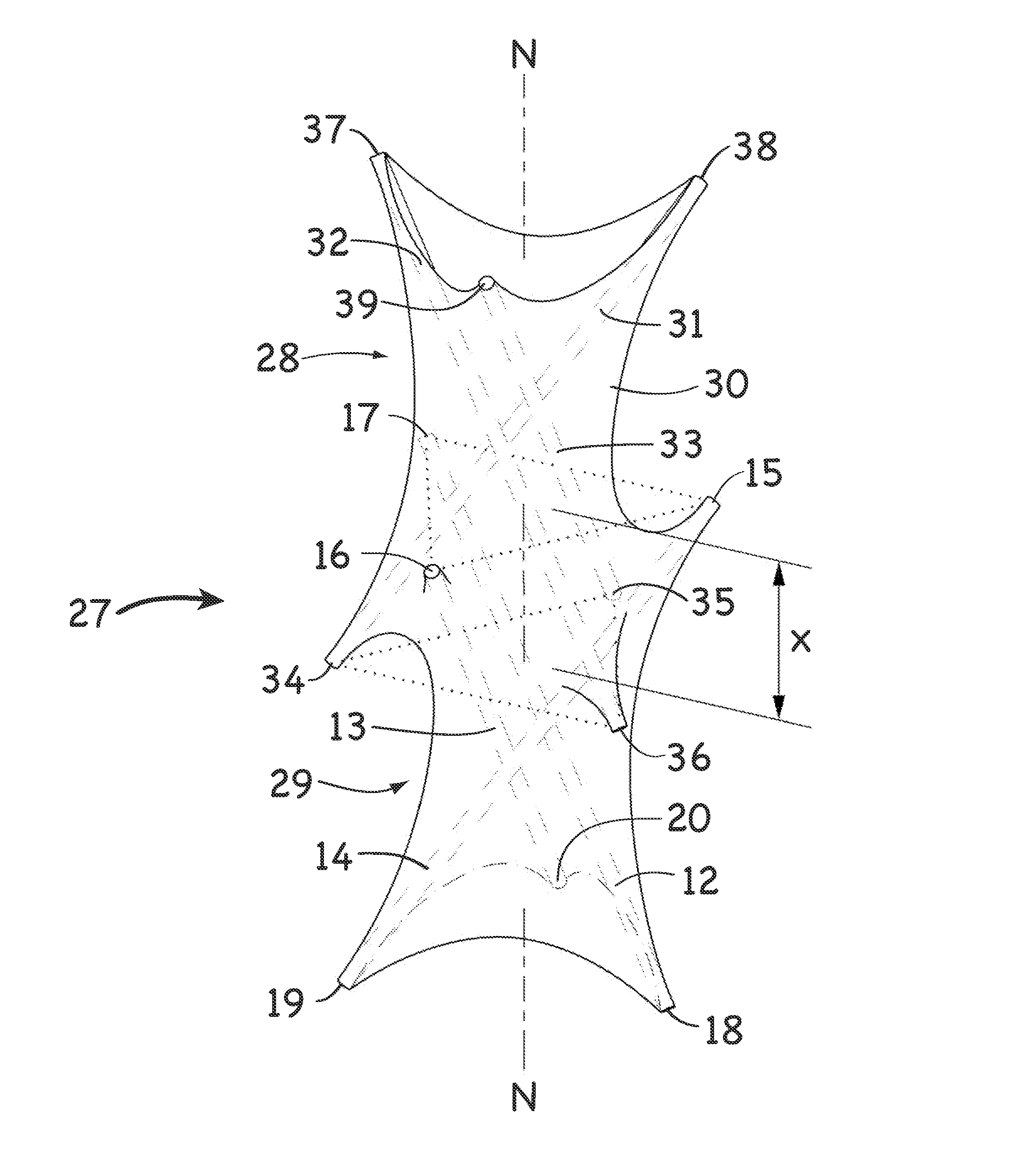
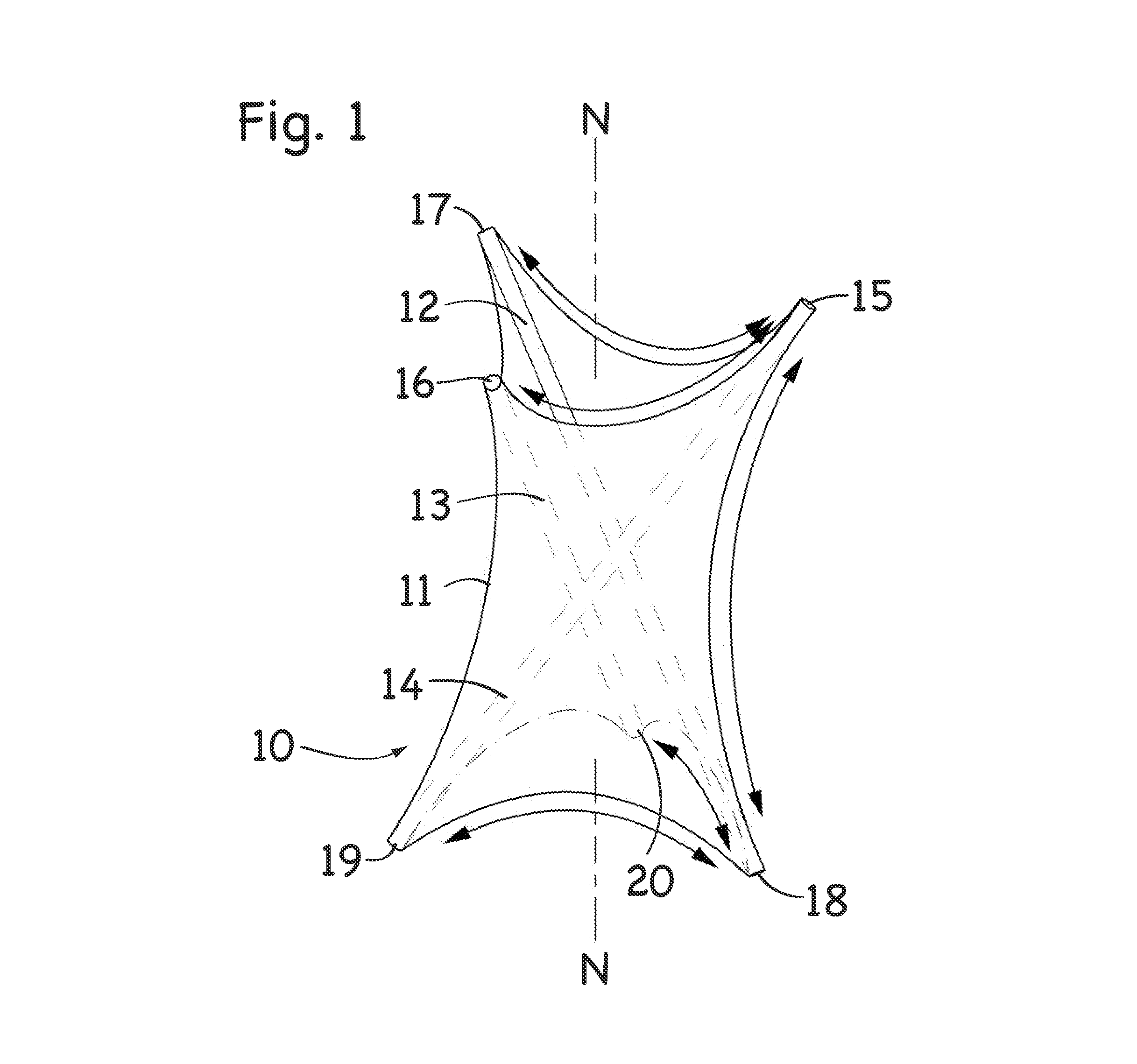
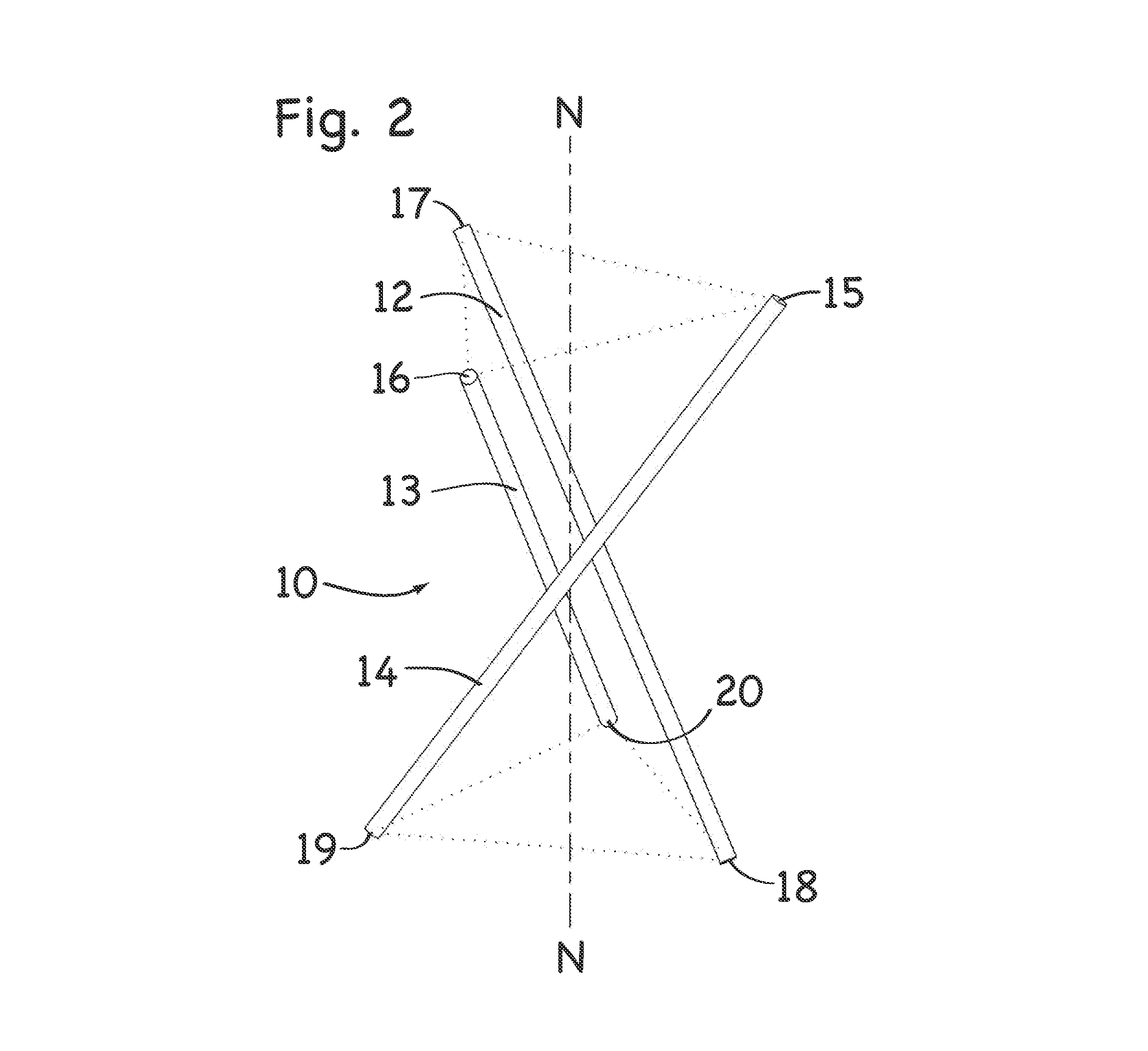
[0050]The tensegrity structures and methods disclosed herein can pursue numerous embodiments within the scope of the invention. However, to ensure that one skilled in the art will be able to understand and, in appropriate cases, practice the invention, certain preferred embodiments of the broader invention revealed herein are described below and shown in the accompanying drawing figures.

[0051]The present invention was made in view of the present inventor's discovery that a continuous membrane can replace the network of linear tension members as a structural component for a particular class of continuous tension, discontinuous compression structures. Under embodiments of the present invention, for example, a continuous pre-stressed membrane can be combined with repetitive, overlapping, and interweaving arrangements of discontinuous compression members to create tubular structures of variable length. The structures and methods disclosed herein substitute a continuous surface for the o...


PUM


Abstract

A tensegrity structure with one or more tensegrity units formed by a membrane in combination with three or more elongate compression members obliquely disposed in a spiral relationship in compression within the membrane. The ends of the compression members within each tensegrity unit and in adjacent tensegrity units are spaced from one another, and the compression members of adjacent tensegrity units overlap along a longitudinal dimension. The membrane forms anticlastic curves and has variable double curvature between ends of compression members. Multiple tensegrity units can form a column, which can be tapered, curved, or otherwise constructed.

Description

PRIORITY[0001]Provisional Application No. 61 / 427,890, filed Dec. 29, 2010FIELD OF THE INVENTION[0002]This invention relates generally to structural frameworks. More particularly, disclosed herein is a novel and improved structure of elongate compression members placed within a membrane in tension to create a self supporting structure with the compression members separated from one other and retained by the membrane.BACKGROUND OF THE INVENTION[0003]The present invention forms part of a well established class of structures often referred to as tensegrity structures, possessing characteristics of discontinuous compression and continuous tension, where elongate members are separately placed either in tension or compression to form a self-supporting lattice. These types of structures achieve significant weight-to-strength ratios by eliminating compression members from the structural framework and replacing them with tension members wherever possible. Tensegrity structures take advantage ...

Claims


Application Information

Patent Timeline
Patent Type & Authority Patents(United States)
IPC IPC(8): E04B1/12E04H12/18E04B7/08E04H12/00
CPCE04B1/12E04B7/08E04H12/00E04H12/18E04B2001/1996E04B1/34E04B1/19
Inventor NADEAU, GERARD, F.
Owner NADEAU GERARD F
Why Eureka
Try Eureka