In-mould labelled container

a container and moulding technology, applied in the field of food substance packaging, can solve the problems of over-dimensioning of existing packages, inoptimized rigidity-to-weight ratio, and excessive packaging material use, and achieve the effect of improving the wetting of coffee powder

Inactive Publication Date: 2014-09-16
SOC DES PROD NESTLE SA
View PDF55 Cites 8 Cited by
  • Summary
  • Abstract
  • Description
  • Claims
  • Application Information

AI Technical Summary

Benefits of technology

[0028]It was found that due to a higher cross section in the pillar that is opposite the injection point, relatively to vertical symmetry axis of the container, the molten material filling the mould at the time the injection process is on-going will flow preferentially through the mould channel corresponding to the pillar having the widest cross section, such that it compensates the fact that the injection point is farther away from this particular pillar mould channel and therefore the molten material has a longer way to go from the said injection point to the said pillar mould channel. In this way, it was found that it is possible to equilibrate the flow of molten material filling the mould in the upper part of the container structure.
[0033]In some instances, it can be beneficial for the support structure that it comprises predetermined weakened zones. This will allow a user to compress or scrap the container after usage, so that it can be more easily disposed of and recycled, in a more compact format. The weakened zone will facilitate the compression of the container after usage, in a predetermined manner.
[0034]Advantageously, the in-mould label can be made at least partially transparent or translucent, so as to allow a user to verify the contents. This can also be particularly beneficial during manufacturing, so as to allow a proper quality control of the manufactured container, for instance to check on line that the container is properly filled, with the correct ingredient, and with an appropriate quantity of the said ingredient.
[0038]In one additional possibility, the dividing wall is pierced with at least one but preferably a plurality of holes. Such a pierced dividing wall can be used for example to hold under pressure a mass of roast and ground powdered coffee in the lower compartment created inside the container chamber. Such a construction will allow preparing an espresso-like coffee beverage, as the pierced dividing wall will allow dividing the flow of fluid and improving the wetting of the coffee powder by said fluid, along with the principle described and claimed in the applicant's former European patent n ° EP 1784344 B1.

Problems solved by technology

Most of the existing packages are over-dimensioned and / or use too much packaging material.
In particular, their rigidity-to-weight ratio is not optimized.
Moreover, certain food substances can lose their particular characteristics due to loss of gases or aroma, e.g. carbonated drinks or coffee powder, or need to be kept dry and inaccessible to oxygen and moisture to maintain freshness, e.g. coffee or milk powder.
One drawback of a flexible container is that it requires an external support for holding liquids in particular hot liquids and / or liquids under pressure.
However, the above outlined mono- or multilayered design of packaging containers suffers several drawbacks such as its relatively high weight, high manufacturing costs and poor recycling properties.
If the capsule presents structural defects or deformations, there is a risk that the capsule is not properly maintained inside the extraction chamber of the machine, and leakage can appear, or the capsule can even be damaged during the pressure build-up.
It was found by the applicant that with the in-mould labelled containers and manufacturing methods for making in-mould labelled containers known in the art, the upper portion of the rigid structure can present defects, particularly when the said structure comprises at least three pillars disposed at an equal distance from one another across the periphery of said structure, and when the structure comprises a lower side which is closed except for a central dispensing opening.
So far, no appropriate solution was found in such cases, and the known in-mould labelled containers of the art present defects which can be particularly negative and even dangerous when the container is a capsule for use in a beverage preparation machine that injects a fluid under pressure in the said capsule.
In such instances, due to the pressure build-up, the zones of the capsule which present defects can be damaged so that leakage will appear in the machine.
In some cases, this will lead to poor quality of the final product as a certain quantity of the fluid that is supposed to extract or dissolve the capsule contents, will leak outside.
In some more serious cases though, the leakage of fluid under pressure can lead to splashes outside of the beverage preparation machine, onto the consumer, which is of course particularly undesirable, especially when the said fluid is hot.
Such damages to the capsule have been analyzed by the applicant, who found that this is due to delamination of the label in zones of the capsule where the rigid structure does not have sufficient material.
Such imperfections in the structure and / or surface of the label lead to leakage when pressure inside the capsule builds up.

Method used


Image

  • In-mould labelled container
  • In-mould labelled container

Examples


Embodiment Construction

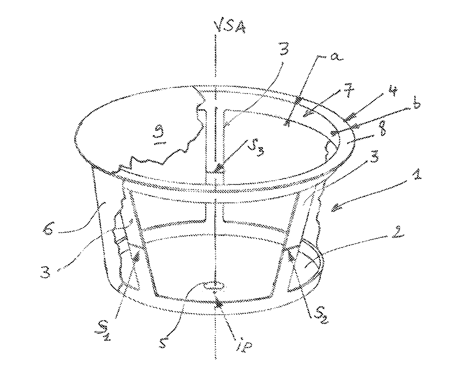
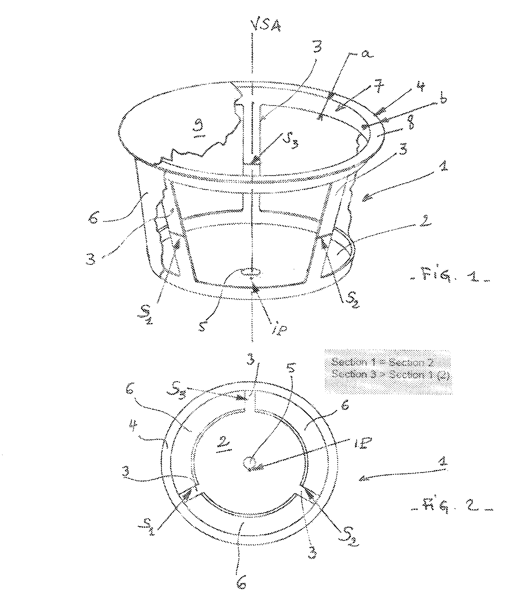
[0049]The capsule according to the invention comprises a semi-rigid structure 1 that is injection moulded, as shown in FIG. 1 and FIG. 2.

[0050]Said capsule is meant for use in a food preparation machine, and comprises the rigid or semi-rigid structure 1 with a lower side 2, at least three substantially vertical pillars 3 extending from the lower side 2 and linked to a circular upper frame 4 which defines the surroundings of the container top side, the pillars 3 having cross-sections S1, S2 and S3, the lower side 2 being a solid wall that comprises a through hole 5 as a dispensing opening for the container, that is centred across the vertical symmetry axis VSA of said container.

[0051]The capsule further comprises a label 6 attached to the outer surface of the lower side 2, and attached also to the outer surface of the pillars 3 and of the upper circular frame 4. The label 6 thus forms an envelope that defines capsule side walls.

[0052]The capsule is manufactured according to known in-...


PUM

PropertyMeasurementUnit
pressureaaaaaaaaaa
pressureaaaaaaaaaa
pressuresaaaaaaaaaa

Abstract

The present invention concerns an injection-molded capsule for use in a food preparation machine, said capsule for use in a food preparation machine comprising: (i) a structure (1) with a lower side (2), at least three pillars (3) extending from the lower side and linked to a circular upper frame (4) which defines the surroundings of the capsule top side, the pillars (3) having cross-sections S1, S2 and S3, the lower side (2) being a solid wall that comprises a dispensing opening (5) and is centered across the vertical symmetry axis VSA of said capsule, and (ii) a label (6) attached to the outer surface of the lower side (2), pillars (3) and upper circular frame (4), thus forming an envelope that defines capsule side walls, characterized in that the injection point IP of the capsule is off-centered in the vicinity of said dispensing opening (5), opposed the pillar (3) having a cross-section S3 relatively to the axis VSA, and in that S1=S2 and S3>S1.

Description

CROSS REFERENCE TO RELATED APPLICATIONS[0001]The present application is a National Stage of International Application No. PCT / EP2011 / 063859, filed on Aug. 11, 2011, which claims priority to European Patent Application No. 10173498.6, filed Aug. 20, 2010, the entire contents of which are being incorporated herein by reference.FIELD OF THE INVENTION[0002]The present invention relates to a packaging for storing food substance. More particularly, the invention relates to a light-weight container and comprising at least two components of different rigidity, and especially a capsule for preparation of a beverage in a food preparation machine.BACKGROUND OF THE INVENTION[0003]Solid and liquid food substances are usually stored in food-grade liquid-tight containers typically made of plastic materials. The container may be a functional package such as a single-use capsule for preparing a beverage or a cartridge for feeding a beverage production machine with soluble coffee powder or coffee mix...

Claims


Application Information

Patent Timeline
Patent Type & Authority Patents(United States)
IPC IPC(8): B65D85/812B29C45/00B29C45/14B29D25/00B29L31/00B65D85/804B65D85/816
CPCB29D25/00B29C45/0046B65D85/8043B65D85/804B65D85/816B29C2045/14918B29C45/14836B29C45/14475B65D2565/385B29L2031/712B65D25/00B65D85/8058B29C45/00B29C45/14B65D15/00
Inventor FABOZZI, THIERRY JEAN ROBERTHENTZEL, STEPHANE
Owner SOC DES PROD NESTLE SA
Why Eureka
Try Eureka