Bonding structure of multilayer copper bonding wire

a multi-layer copper and bonding wire technology, applied in the direction of sustainable manufacturing/processing, conductors, final product manufacturing, etc., can solve the problems of low bonding strength, corrosion or the like easily occurring on the wire surface, and the copper bonding wire has not been actively used. , to achieve the effect of superior low loop bondability and ball bondability, and low material cos

Active Publication Date: 2014-09-16
NIPPON STEEL CHEMICAL CO LTD +1
View PDF11 Cites 42 Cited by
  • Summary
  • Abstract
  • Description
  • Claims
  • Application Information

AI Technical Summary

Problems solved by technology

However, since gold is expensive, there is desired a bonding wire that is made of an other kind of metal and whose material cost is inexpensive.
However, such copper bonding wire has imposed, for example: a problem where a bonding strength decreases due to an oxidation on a wire surface; and a problem where a corrosion or the like easily takes place on the wire surface when encapsulated by resin.
These problems are also the reasons why the copper bonding wire has not been actively put to practical use for LSI purposes.
In general, while an advantage of performing normal bonding is that there can be achieved a high productivity, a disadvantage thereof is that the method is not suitable for performing low loop bonding.
Meanwhile, while an advantage of performing reverse bonding which was originally put to practical use for multilayer chip purposes is that low loop bonding can be performed relatively easily therewith, a disadvantage thereof is that a decreased productivity is resulted due to the fact that the method includes an additional step for forming the ball bump.
An FOW (Film On Wire) method which is a typical example of the aforementioned new packaging method, does not employ spacers, thus expectedly resulting in a low cost.
As for a conventional bonding wire having a single-layer structure (referred to as “single layer bonding wire” hereunder), although adding an alloying element(s) is effective in improving, for example, a tensile strength, a strength of the bonded portion and a reliability, there exists a concern that improvements in the properties of the wire may be limited to a certain extent.

Method used


Image

  • Bonding structure of multilayer copper bonding wire
  • Bonding structure of multilayer copper bonding wire
  • Bonding structure of multilayer copper bonding wire

Examples


working examples

[0105]Working examples are described hereunder.

[0106]Raw materials of a multilayer copper bonding wire were as follows. That is, there was used a Cu having a purity of about 99.99% by mass or higher, which was a high-purity material. As for materials of an outer layer, there were prepared Pd, Au, Ag and Pt, all of which had a purity of about 99.99% by mass or higher. The multilayer copper bonding wire was manufactured as follows. That is, as a core member, there was prepared in advance a high-purity copper wire whose wire diameter had been thinned down to a certain extent. Further, on a surface of such copper wire, there was then formed the outer layer made of a different metal(s), through electrolytic plating. Here, an initial film thickness of the outer layer was calculated based on a thinned film thickness thereof at a final wire diameter. A heat treatment was carried out in a range of 200-600° C., if promoting formations of concentration gradients and generations of diffusion la...


PUM

PropertyMeasurementUnit
thicknessaaaaaaaaaa
thicknessaaaaaaaaaa
thicknessaaaaaaaaaa

Abstract

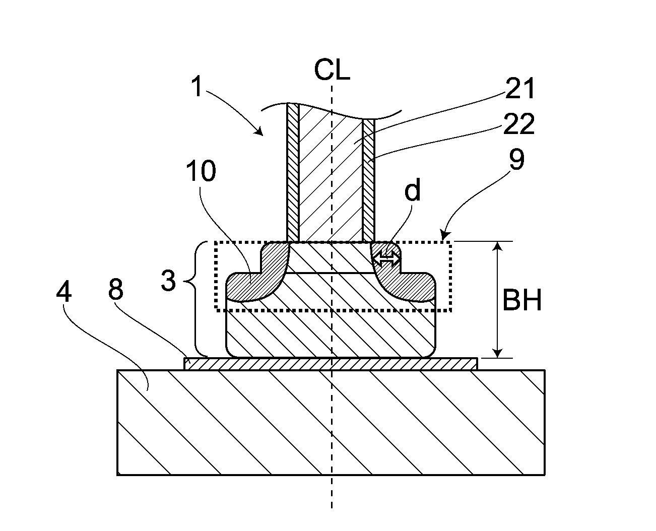
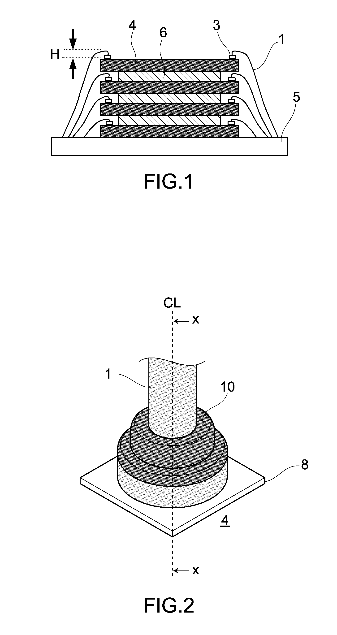
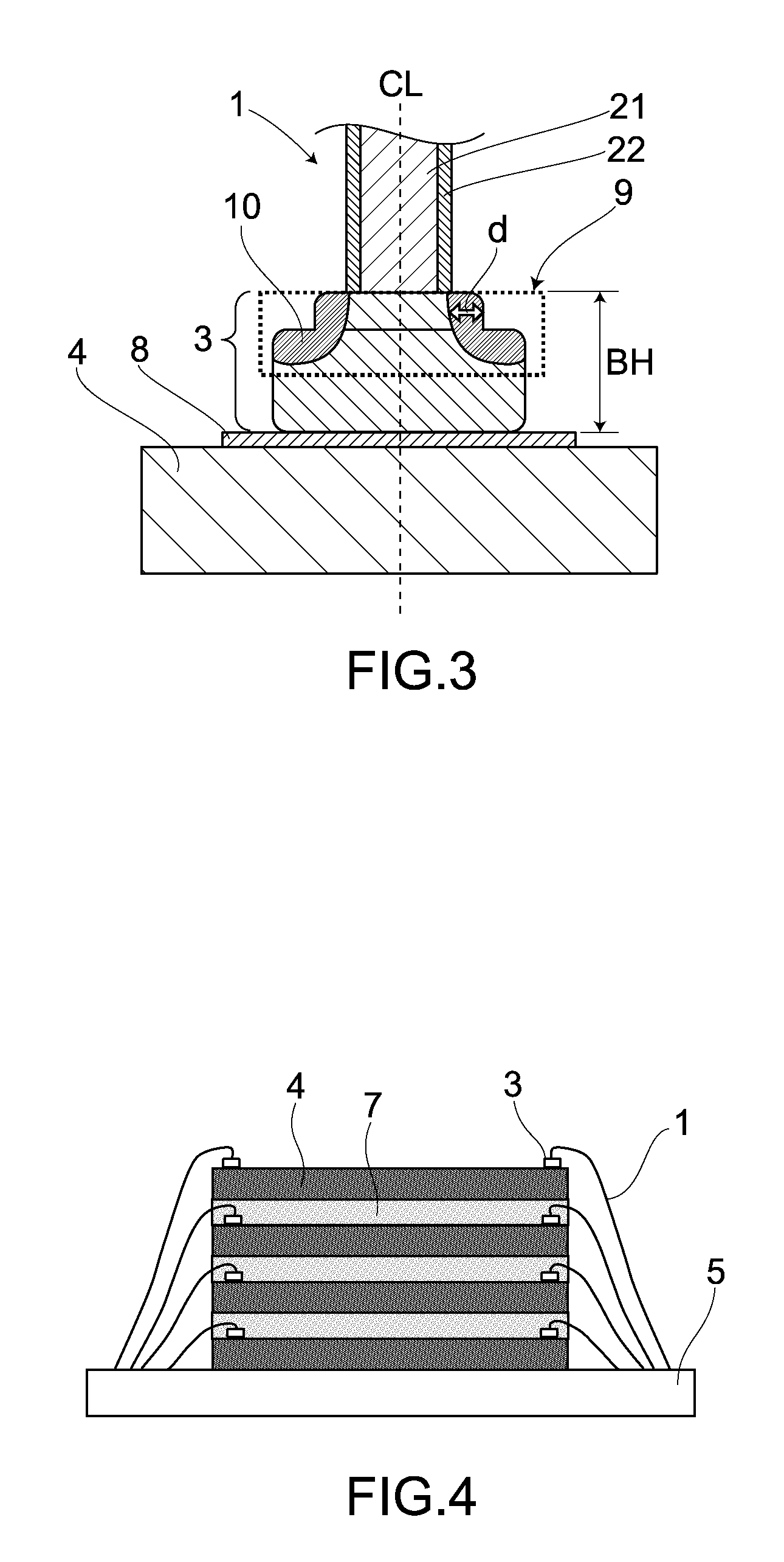
A bonding structure of a ball-bonded portion is obtained by bonding a ball portion formed on a front end of a multilayer copper bonding wire. The multilayer copper bonding wire includes a core member that is mainly composed of copper, and an outer layer that is formed on the core member and is mainly composed of at least one noble metal selected from a group of Pd, Au, Ag and Pt. Further, a first concentrated portion of such noble metal(s) is formed in a ball-root region located at a boundary with the copper bonding wire in a surface region of the ball-bonded portion.

Description

CROSS-REFERENCE TO RELATED APPLICATIONS[0001]This is a U.S. national phase application under 35 U.S.C. §371 of International Patent Application No. PCT / JP2011 / 072397, filed on Sep. 29, 2011, and claims priority to Japanese Patent Application No. 2010-224213, filed Oct. 1, 2010. The International Application was published on Apr. 5, 2012 as International Publication No. WO 2012 / 043727 under PCT Article 21(2). The entire contents of these applications are hereby incorporated by reference.TECHNICAL FIELD[0002]The present invention relates to a bonding structure of a multilayer copper bonding wire.BACKGROUND ART[0003]As a bonding wire (for performing wire bonding) used to join an electrode on a semiconductor device to an external terminal, there has been mainly used a thin wire (bonding wire) having a wire diameter of about 10-50 μm. A thermocompression bonding technique combined with an ultrasonic wave, is generally employed to perform wire bonding. Meanwhile, there are also used, for ...

Claims


Application Information

Patent Timeline
Patent Type & Authority Patents(United States)
IPC IPC(8): H01L23/48B23K20/00H01B1/02H01L23/00H01L25/065
CPCH01B1/026H01L25/0657B23K20/007H01L24/43H01L24/85H01L24/48H01L23/48H01L24/78H01L24/45H01L2924/01024H01L2224/76268H01L2924/01029H01L2224/45664H01L2924/01327H01L2224/48227H01L2224/45644H01L2225/0651H01L2224/48799H01L2924/01045H01L2224/45565H01L2924/01006H01L2224/32145H01L2924/01078H01L2224/45669H01L2924/01014H01L2924/01013H01L2224/48599H01L2924/01046H01L2924/10253H01L2924/01033H01L2224/781H01L2224/4851H01L2924/01082H01L2924/01015H01L2224/85045H01L2224/48091H01L2224/4845H01L2924/01028H01L2924/01047H01L2224/05624H01L2924/01079H01L2224/73265H01L2224/45147H01L2224/45015H01L2924/12041H01L2224/45639H01L2225/06565H01L2224/48465H01L2224/43H01L2924/00015H01L2224/48247H01L2224/85205H01L2224/43848H01L2224/48511H01L2224/78268H01L2924/3025H01L24/73H01L2224/45572H01L2224/48824H01L2224/85203H01L2224/85439H01L2224/85444H01L2224/85447H01L2224/85464H01L2924/00011Y02P70/50H01L2224/45678H01L2924/00014H01L2924/00012H01L2924/00H01L2224/45144H01L2924/20752H01L2924/01204H01L2924/20108H01L2924/20109H01L2924/2011H01L2924/20111H01L2924/01083H01L2924/013H01L2924/00013
Inventor UNO, TOMOHIROYAMADA, TAKASHIIKEDA, ATSUO
Owner NIPPON STEEL CHEMICAL CO LTD
Why Eureka
Try Eureka