
Gas turbine combustor including a transition piece flow sleeve wrapped on an outside surface of a transition piece

a technology of gas turbine combustor and flow sleeve, which is applied in the direction of stators, machines/engines, light and heating apparatus, etc., can solve the problems of reducing the strength of the surrounding member of the corner portion of the flow sleeve stretching and deformation of the flow sleeve in and reducing the strength of the surrounding member of the corner portion of the transition piece flow sl

Active Publication Date: 2014-09-23
MITSUBISHI POWER LTD
View PDF13 Cites 1 Cited by
  • Summary
  • Abstract
  • Description
  • Claims
  • Application Information

AI Technical Summary

Benefits of technology

The present invention is about a gas turbine combustor that aims to improve the cooling and reliability of the transition piece flow sleeve, which is a component often used in gas turbine engines. The invention achieves this by introducing cross flows of air through air holes in the corner portion of the transition piece flow sleeve, which can weaken the effect of collision of jet flow to the transition piece and reduce impingement cooling. This results in improved cooling and reduced deformation and cracking in the transition piece flow sleeve, ultimately improving the reliability of the gas turbine combustor.

Problems solved by technology

Therefore, a problem arises that at the time of press molding, the air holes formed in the corner portion of the transition piece flow sleeve are stretched and deformed.
And, when the deformation amount of the air holes is large, there is a possibility that the surroundings of the air holes may be cracked.
Therefore, if air holes are formed in the corner portion of the transition piece flow sleeve, the strength of the surrounding member of the corner portion of the transition piece flow sleeve is reduced, thus there is a possibility that due to the stress in operation, there is a possibility that the main unit of the transition piece flow sleeve may be deformed.

Method used


Image

  • Gas turbine combustor including a transition piece flow sleeve wrapped on an outside surface of a transition piece
  • Gas turbine combustor including a transition piece flow sleeve wrapped on an outside surface of a transition piece
  • Gas turbine combustor including a transition piece flow sleeve wrapped on an outside surface of a transition piece

Examples


embodiment 1

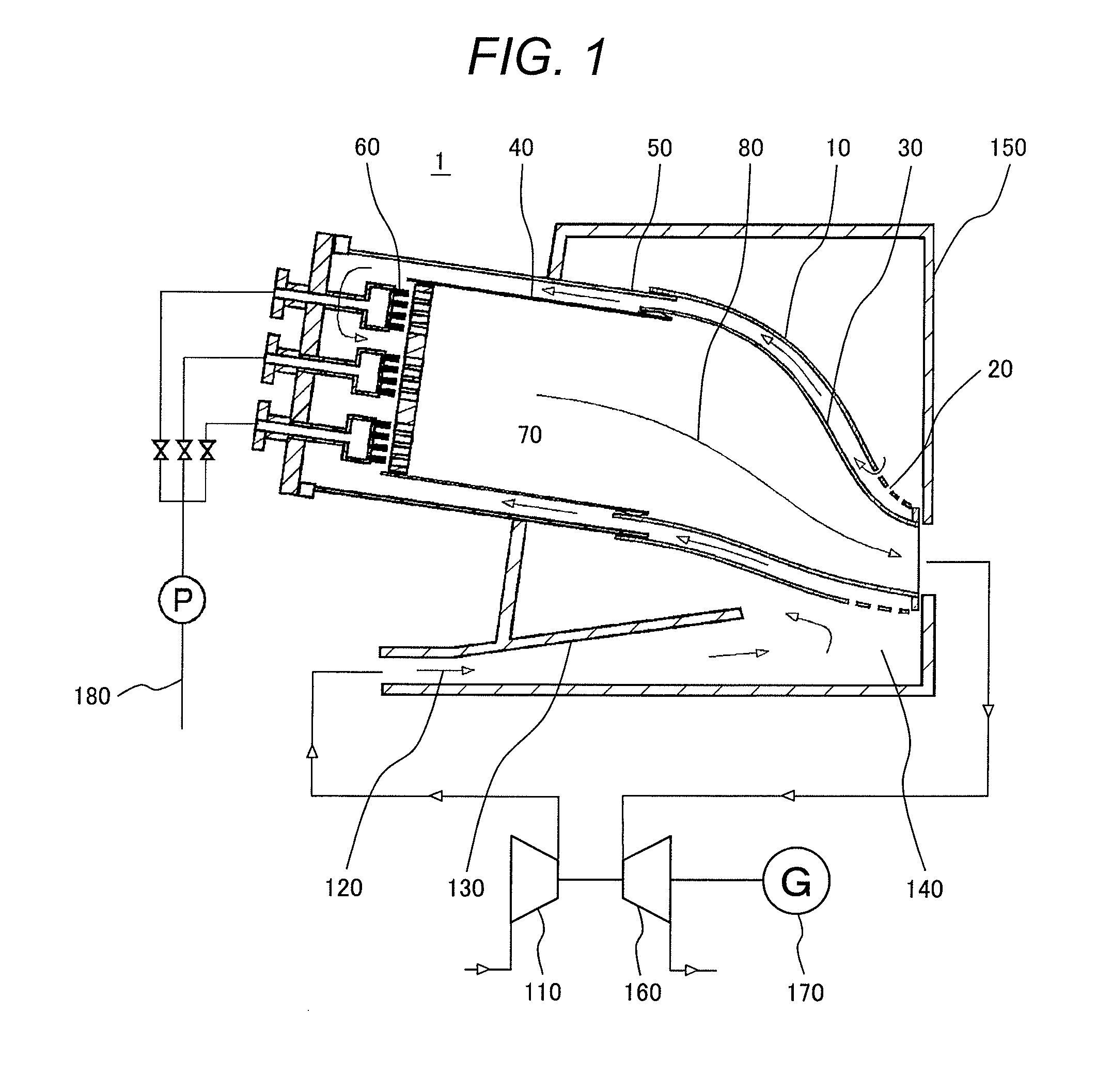
[0036]The gas turbine combustor that is the first embodiment of the present invention will be explained below by referring to FIGS. 1 to 4.

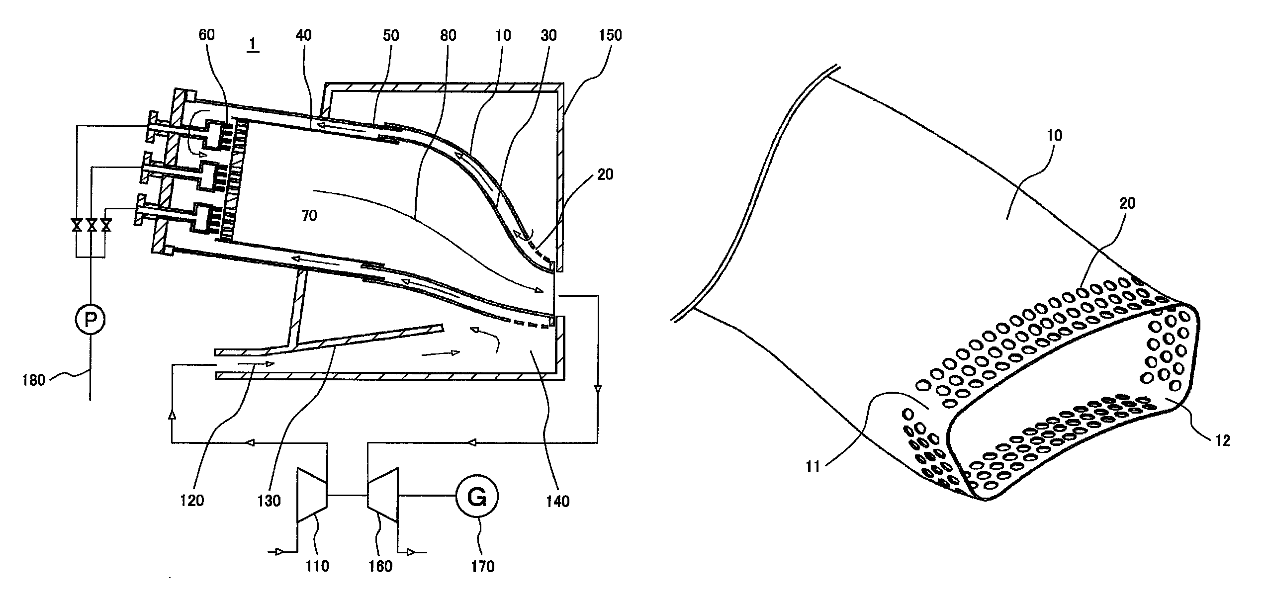
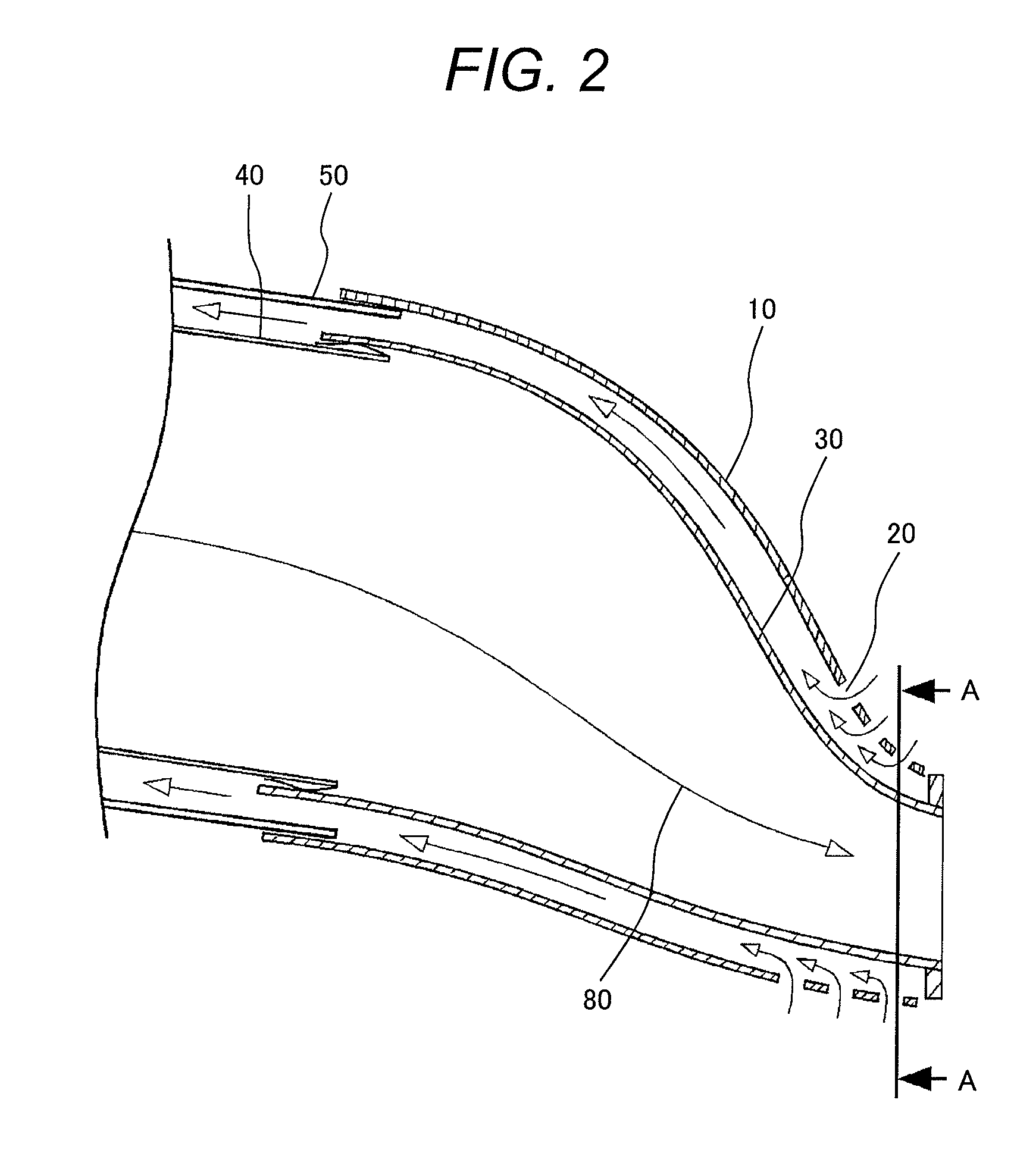
[0037]FIG. 1 is a schematic diagram showing the constitution of the gas turbine unit to which a gas turbine combustor 1 of the first embodiment of the present invention is applied. As shown in FIG. 1, high-pressure air 120 compressed and introduced by an air compressor 110 is introduced into a plenum chamber 140 via a diffuser 130 and flows into the gap between a transition piece 30 and a transition piece flow sleeve 10 from air introduction holes 20 formed in the transition piece flow sleeve 10 composing the gas turbine combustor 1.

[0038]The high-pressure air 120 flowing into the gap between the transition piece 30 and the transition piece flow sleeve 10 flows through the gap between a liner 40 and a liner flow sleeve 50 arranged on the concentric circle on the outer periphery of the liner, then reverses the flow, is mixed with fuel injected fro...

embodiment 2

[0068]Next, the gas turbine combustor 1 which is the second embodiment of the present invention will be explained by referring to FIGS. 11 to 13. The gas turbine combustor 1 which is the second embodiment of the present invention is the same in the basic constitution as for the gas turbine combustor 1 of the first embodiment shown in FIGS. 1 to 4, so that the explanation of the common constitution to the two is omitted and the different portions will be explained.

[0069]As shown in FIGS. 11 to 13, in the gas turbine combustor 1 of this embodiment, in the corner portions 11 and 12 of the transition piece flow sleeve 10, air holes 21 with a diameter smaller than that of the air holes 20 in other regions other than the corner portions 11 and 12 are formed.

[0070]FIG. 13 shows an external view of the exit portion in the single state of the transition piece flow sleeve 10, wherein the air holes 21 with a diameter smaller than that of the air holes 20 in other regions other than the corner ...


PUM


Abstract

A gas turbine combustor comprising a fuel nozzle for injecting mixed gas of fuel and air, a cylindrical liner for burning and reacting the mixed gas of fuel and air in a combustion chamber, a transition piece which is a flow path for leading combustion gas generated in the liner to turbine blades, and a transition piece flow sleeve for wrapping an outside surface of the transition piece,wherein a plurality of air introduction holes for introducing air into the transition piece flow sleeve are formed in regions of the transition piece flow sleeve excluding regions which are corner portions of the transition piece flow sleeve in a sectional direction thereof.

Description

CLAIM OF PRIORITY[0001]The present application claims priority from Japanese patent application JP 2010-225391 filed on Oct. 5, 2010, the content of which is hereby incorporated by reference into this application.BACKGROUND OF THE INVENTION[0002]1. Field of the Invention[0003]The present invention relates to a gas turbine combustor and more particularly to a structure of a gas turbine combustor intending to improve the reliability and cooling property of a transition piece for leading combustion gas generated in a combustion chamber of the gas turbine combustor to the turbine blades.[0004]2. Description of Related Art[0005]The transition piece composing the gas turbine combustor is a flow path for leading high-temperature and high-pressure combustion gas generated by an oxidation reaction of fuel and air in the combustion chamber of the gas turbine combustor to the turbine blades.[0006]The transition piece of the gas turbine combustor is a duct having an entrance portion in a circul...

Claims


Application Information

Patent Timeline
Patent Type & Authority Patents(United States)
IPC IPC(8): F02C1/00F02G3/00F01D9/02F23R3/04
CPCF23R3/04F01D9/023F23R2900/03044F05D2260/201F23R3/28
Inventor SAITOU, TAKEOWATANABE, YASUYUKIYOSHIDA, SHOUHEI
Owner MITSUBISHI POWER LTD
Learn More