Rotation angle sensor

a technology of rotation angle and sensor, which is applied in the direction of instruments, resistance/reactance/impedence, force/torque/work measurement apparatus, etc., can solve the problems of high manufacturing cost, high volume of mass applications, and problems such as electrically conductive swarfs, etc., and cannot be expected

Active Publication Date: 2014-10-07
ROBERT BOSCH GMBH
View PDF20 Cites 3 Cited by
  • Summary
  • Abstract
  • Description
  • Claims
  • Application Information

AI Technical Summary

Benefits of technology

[0016]With the aid of the present invention, a contactless measuring method may be implemented which is not subject to friction and which does not generate noise. The provided measuring system has a compact, robust design and is manufacturable in a cost-effective manner, since in direct comparison to magnetically measuring systems, the use of magnets, Hall ICs, flux conductors, etc., and therefore, expensive components, is not necessary.

Problems solved by technology

However, for these types of sensors, high manufacturing costs result for large, high-volume mass applications due to complicated and expensive components, for example an oppositely polarized magnet ring or the metallic flux conducting elements necessary for conducting the magnetic flux.
Thus, problems with electrically conductive swarfs, among other problems, are not to be expected.

Method used


Image

  • Rotation angle sensor
  • Rotation angle sensor
  • Rotation angle sensor

Examples


Embodiment Construction

[0039]The present invention is schematically illustrated in the figures based on a specific embodiment, and is described in greater detail below with reference to the figures.

[0040]The figures are described in an interrelated and all-encompassing manner, with identical components being denoted by the same reference numerals.

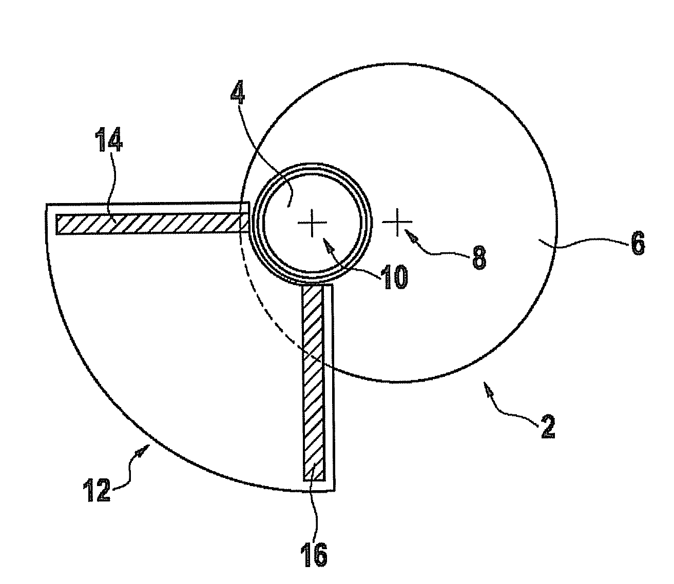
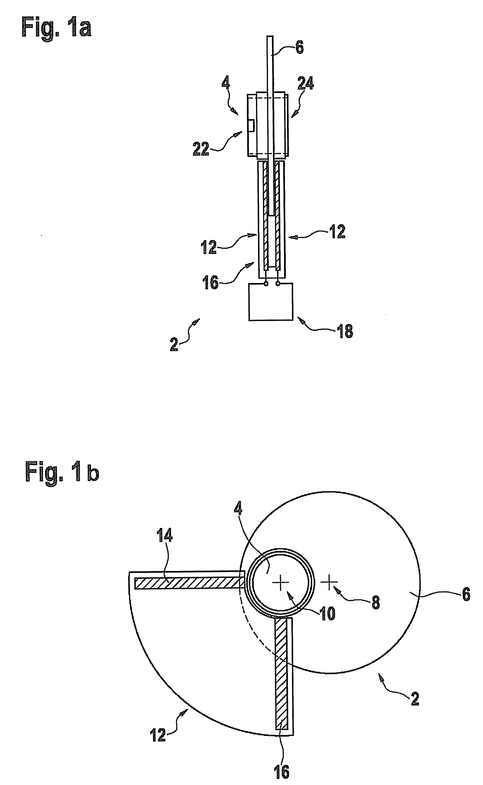
[0041]FIG. 1 shows a schematic illustration of a first example of a rotation angle sensor 2 according to the present invention in a top view (FIG. 1b) and in a side view (FIG. 1a). A flat, circular disk 6 made of plastic is attached to a shaft 4; disk 6 together with shaft 4 have a shared axis or a shared pivot point which has a distance from a center point 8 of disk 6 which is greater than zero. In the present case, the distance corresponds to approximately one-third of the diameter of disk 6. Generally, a distance between one-fourth and one-half of the diameter of disk 6 may be provided. A rotation of shaft 4 causes disk 6 to rotate asymmetrically about axis 10...


PUM

PropertyMeasurementUnit
rotation angleaaaaaaaaaa

Abstract

A rotation angle sensor which has at least one capacitor having capacitor plates and a dielectric designed as a disk. The disk is situated between the capacitor plates, and fills out differently sized surface portions between the capacitor plates, depending on the rotation angle. The rotation angle sensor is designed to determine the rotation angle as a function of a measured value of the capacitance of the at least one capacitor.

Description

FIELD OF THE INVENTION[0001]The present invention relates to a rotation angle sensor, a torque sensor, a method for determining a rotation angle, and a method for determining a torque.BACKGROUND INFORMATION[0002]Magnetic measuring methods are usually used nowadays in the field of torque sensors and rotation angle sensors. One example of such is the TSS-1 torque sensor from Robert Bosch GmbH, in which a magnetic field which changes during a rotary motion is detected using Hall sensors, and a measured signal is converted into a rotation angle signal or a torque signal. These sensors are characterized in particular by their high angular resolution, which may sometimes be less than 0.01°.[0003]However, for these types of sensors, high manufacturing costs result for large, high-volume mass applications due to complicated and expensive components, for example an oppositely polarized magnet ring or the metallic flux conducting elements necessary for conducting the magnetic flux. In additio...

Claims


Application Information

Patent Timeline
Patent Type & Authority Patents(United States)
IPC IPC(8): G01R27/26G01D5/24G01L3/10G01L5/22
CPCG01L3/109G01L3/106G01D5/2405G01L5/221
Inventor LUDWIG, RONNY
Owner ROBERT BOSCH GMBH
Why Eureka
Try Eureka