
Porous polymer scaffolds for neural tissue engineering and methods of producing the same

a polymer scaffold and neural tissue technology, applied in the field of biomedical implants, can solve the problems of hydrogel isotropic nature, model cannot predict changes, no scaffold has yielded complete functional recovery, etc., and achieve the effect of promoting axon outgrowth

Active Publication Date: 2014-11-04
DREXEL UNIV
View PDF0 Cites 6 Cited by
  • Summary
  • Abstract
  • Description
  • Claims
  • Application Information

AI Technical Summary

Problems solved by technology

To date, no scaffold has yielded complete functional recovery, though recent attempts have managed to solve some, but not yet all, of the requirements for an effective scaffold.
They compared their model against varying concentrations of agar solidification and subsequent lyophilization, and found that the model could not predict the changes when the solution was increased from 3% to 10% by weight.
Unfortunately, the researchers tested the Pia mater itself in tension, and then tested gray and white matter, and the gray / white / Pia combination, in compression, which may explain why the Pia mater, with a Young's modulus of 2.3 MPa in tension, only tripled the compressive modulus of the gray / white / Pia combination to 16 kPa.
Unfortunately, after the two weeks the axonal growth regressed, most likely due to the BDNF diffusing away, since the authors did allow that unmodified pHEMA was not suitable for axonogenesis [Bakshi, A., et al., 2004, Journal of Neurosurgery: Spine 1(3):322-329].
The biggest drawback of hydrogels is their isotropic nature.
While they may be highly porous, their physical structure does not lend itself to aligned growth.
Unfortunately, no mention of how tightly compressed or cross-section images of the filaments were reported; thus knowledge of the substrate that the axons were growing on is lacking.
While the morphology of the scaffolds is approaching that of a well-designed scaffold, the authors failed to recognize the importance of matching the mechanical properties of the scaffold.
Unfortunately, the authors did not create channels less than 20 μm wide, so there is it not known whether 15 or 10 μm wide channels would generate longer neurites.

Method used


Image

  • Porous polymer scaffolds for neural tissue engineering and methods of producing the same
  • Porous polymer scaffolds for neural tissue engineering and methods of producing the same
  • Porous polymer scaffolds for neural tissue engineering and methods of producing the same

Examples


experimental examples

[0145]The invention is now described with reference to the following Examples. These Examples are provided for the purpose of illustration only and the invention should in no way be construed as being limited to these Examples, but rather should be construed to encompass any and all variations which become evident as a result of the teaching provided herein.

[0146]Without further description, it is believed that one of ordinary skill in the art can, using the preceding description and the following illustrative examples, make and utilize the present invention and practice the claimed methods. The following working examples therefore, specifically point out the preferred embodiments of the present invention, and are not to be construed as limiting in any way the remainder of the disclosure.

[0147]The following methods and materials were used in the experimental examples presented herein.

Polymer Preparation

[0148]Varying combinations of chitosan and gelatin, each dissolved in 1% (v / v) ac...

example 1

Generation of Chitosan Scaffolds

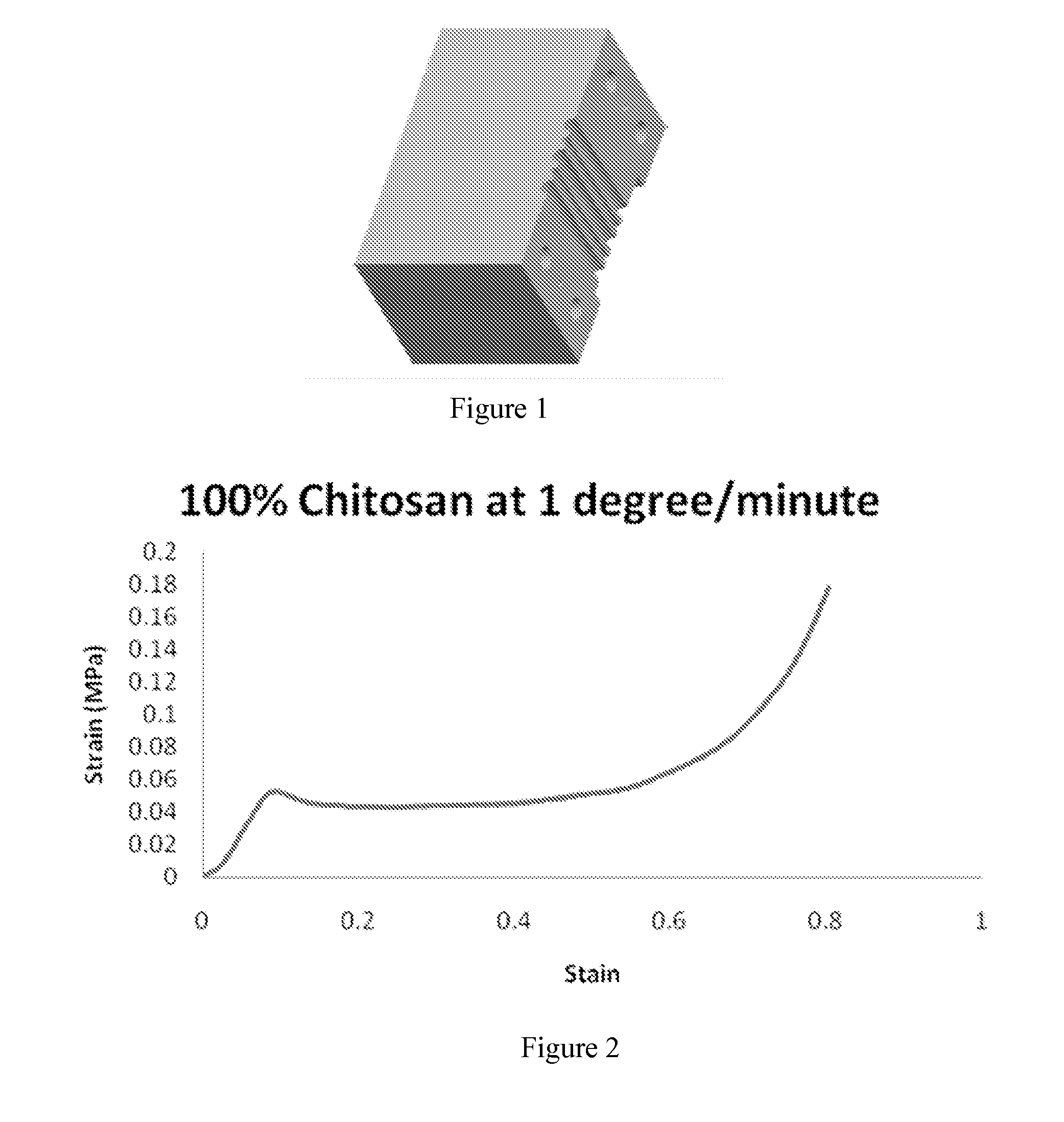
[0165]Demonstrated herein is an analysis of how the freezing rate, from 0.1° C. / m to 10° C. / m, affects the mechanical properties of the resultant chitosan scaffolds. Scaffolds were mechanically evaluated in both dry (ambient air) and wet (soaked in PBS) conditions. FIGS. 30A and 30B depict how the modulus and plateau strength (both MPa) vary according to the freezing rate in dry conditions. For each freezing rate, 3 layers were tested; the middle-height from the sample's bottom of the three layers is given in Table 1.

[0166]

TABLE 1Height (mm) from the bottom of the sample tothe bottom, middle, and top of each layer.LayerBottom of LayerMiddle of LayerTop of LayerTop25.3327.8330.33Middle14.8317.3319.83Bottom4.336.839.33Three layers were mechanically tested from each sample.

[0167]From FIGS. 7A and 7B, one can clearly see the change in values from within each sample; the bottom layer has a consistently higher modulus and plateau, while the top layer perfor...

example 2

Effects of Scaffolds on Neurite Growth

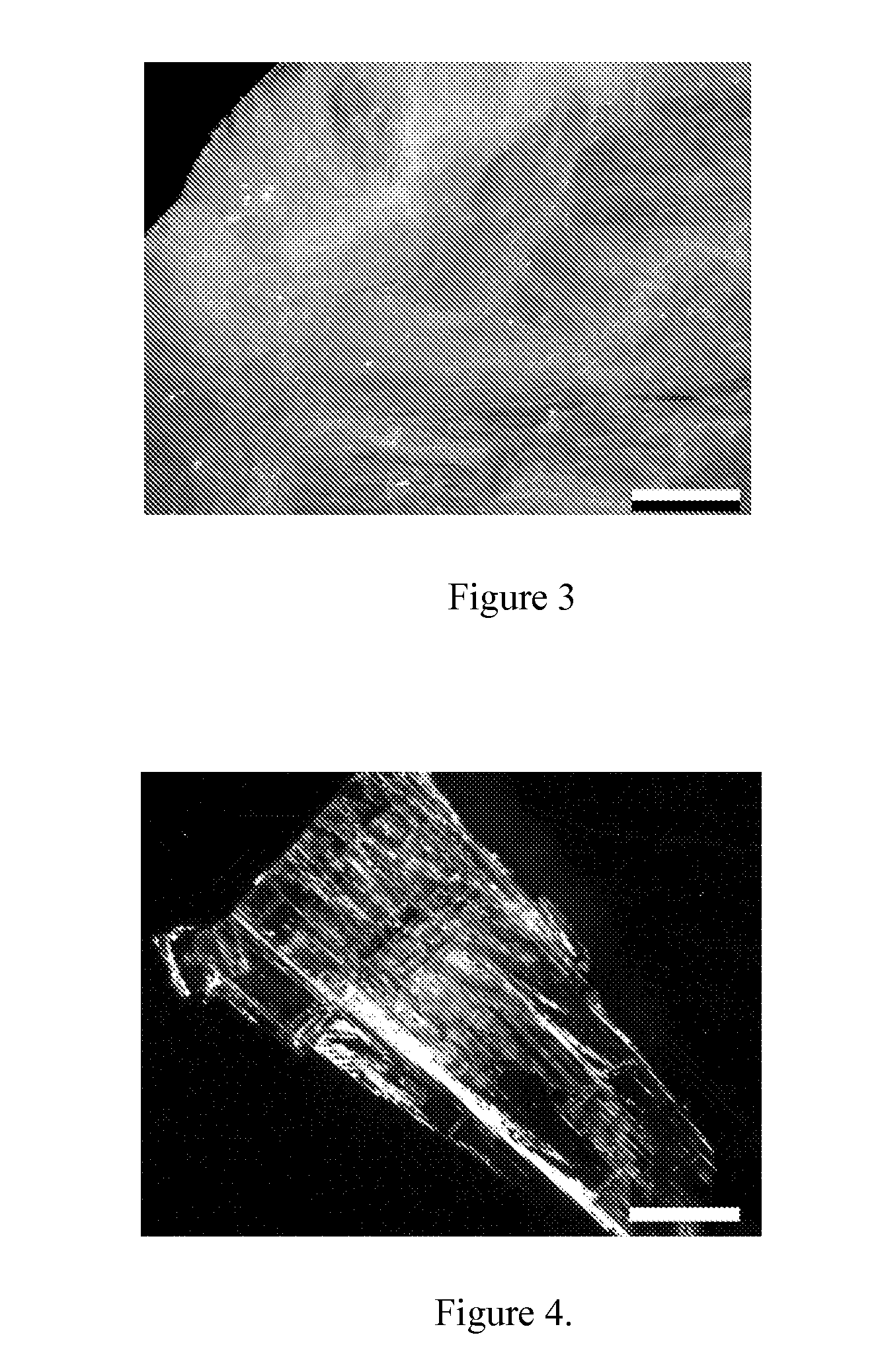
[0185]Having elucidated the structure-property correlations within the samples, and showing that the ridges serve to strengthen the elastic buckling-dominated architecture, the next logical step was to determine the ridge's effect on neurite outgrowth. SEM images of dissociated neurons cultured on the scaffolds (FIGS. 20A through 21B) show the soma (FIG. 20B) nestled between two ridges; neurites extended from the soma linearly, and stay within their respective grooves. One or two neurites were seen to jump from groove to groove, but predominately the neurites were guided by the ridges. FIGS. 21A and 21B show the same neurite growing up onto and then off of the same ridge. FIGS. 20A through 21B are in direct contrast to the controls, where both DRGs (FIG. 22A) and dissociated neurons (22B) were cultured on laminin-coated glass coverslides. Neurites were seen to extend in twisting, random directions from the soma; this was further corroborated by ...


PUM


Abstract

The present invention relates to scaffolds that can physically guide cells, e.g. neurons, while best matching the material properties of native tissue. The present invention also relates to methods of generating such scaffolds, and for the use of such scaffolds, e.g. in spinal cord and peripheral nerve injury repair. The methods of the present invention include a uniquely controlled freeze casting process to generate highly porous, linearly oriented scaffolds. The scaffolds of the present invention not only comprise a highly aligned porosity, but also contain secondary guidance structures in the form of ridges running parallel to the pores to create a series of microstructured and highly aligned channels. This hierarchy of structural guidance aligns and guides neurite outgrowth down the channels created by the ridges, and keep neurites from branching perpendicular to the inter-ridge grooves.

Description

CROSS-REFERENCE TO RELATED APPLICATIONS[0001]The present invention and application claims priority to U.S. Provisional Application Nos. 61 / 418,776, filed on Dec. 1, 2010, and 61 / 474,636, filed on Apr. 12, 2011, the contents of which are each incorporated by reference herein as if each is set forth herein it its entirety.BACKGROUND OF THE INVENTION[0002]Spinal cord injury (SCI) has attracted significant interest in the field of biomedical implants; its challenges range from matching the mechanical values of the host tissue to creating a scaffold capable of physically guiding the growing neurites. To date, no scaffold has yielded complete functional recovery, though recent attempts have managed to solve some, but not yet all, of the requirements for an effective scaffold. A historical summary of these efforts and related developments is presented below.[0003]Cellular solids, being composites of a solid material and a gas phase, can be roughly divided into two broad categories: stretch...

Claims


Application Information

Patent Timeline
Patent Type & Authority Patents(United States)
IPC IPC(8): C12N5/00C12N5/0793
CPCC12N2533/72C12N2537/00C12N5/0619C12N2533/32C12N2533/74C12N2533/52C12N2533/54
Inventor WEGST, ULRIKE G.K.WHEATLEY, MARGARETRIBLETT, BENJAMIN W.FRANCIS, NICOLADONIUS, AMALIE ELIZABETH
Owner DREXEL UNIV
Learn More