Durable, lightweight, and efficient solar concentrator

a solar concentrator and solar energy technology, applied in the direction of heat collector mounting/support, pv power plants, lighting and heating apparatus, etc., can solve the problems of low maximum solar concentration, high cost of tall towers, stringent mirror contour requirements, etc., and achieve the effect of maximizing efficiency and maximizing the intensity of solar radiation inciden

Inactive Publication Date: 2014-11-04
PERSISTENT ENERGY
View PDF58 Cites 4 Cited by
  • Summary
  • Abstract
  • Description
  • Claims
  • Application Information

AI Technical Summary

Benefits of technology

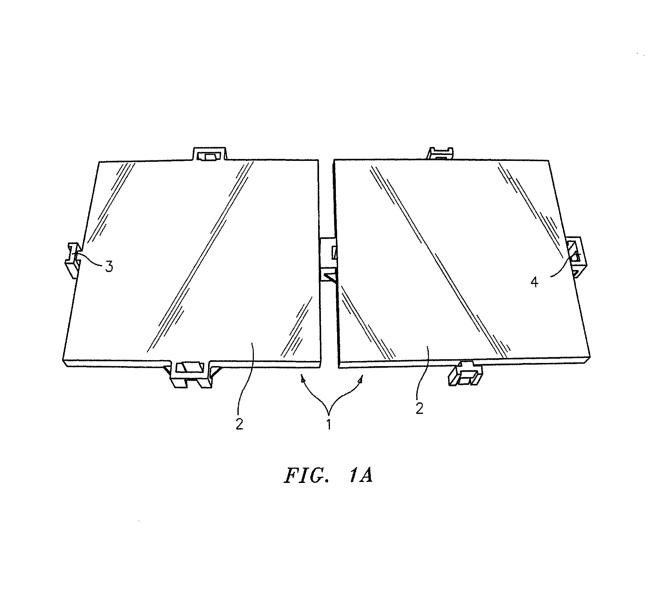
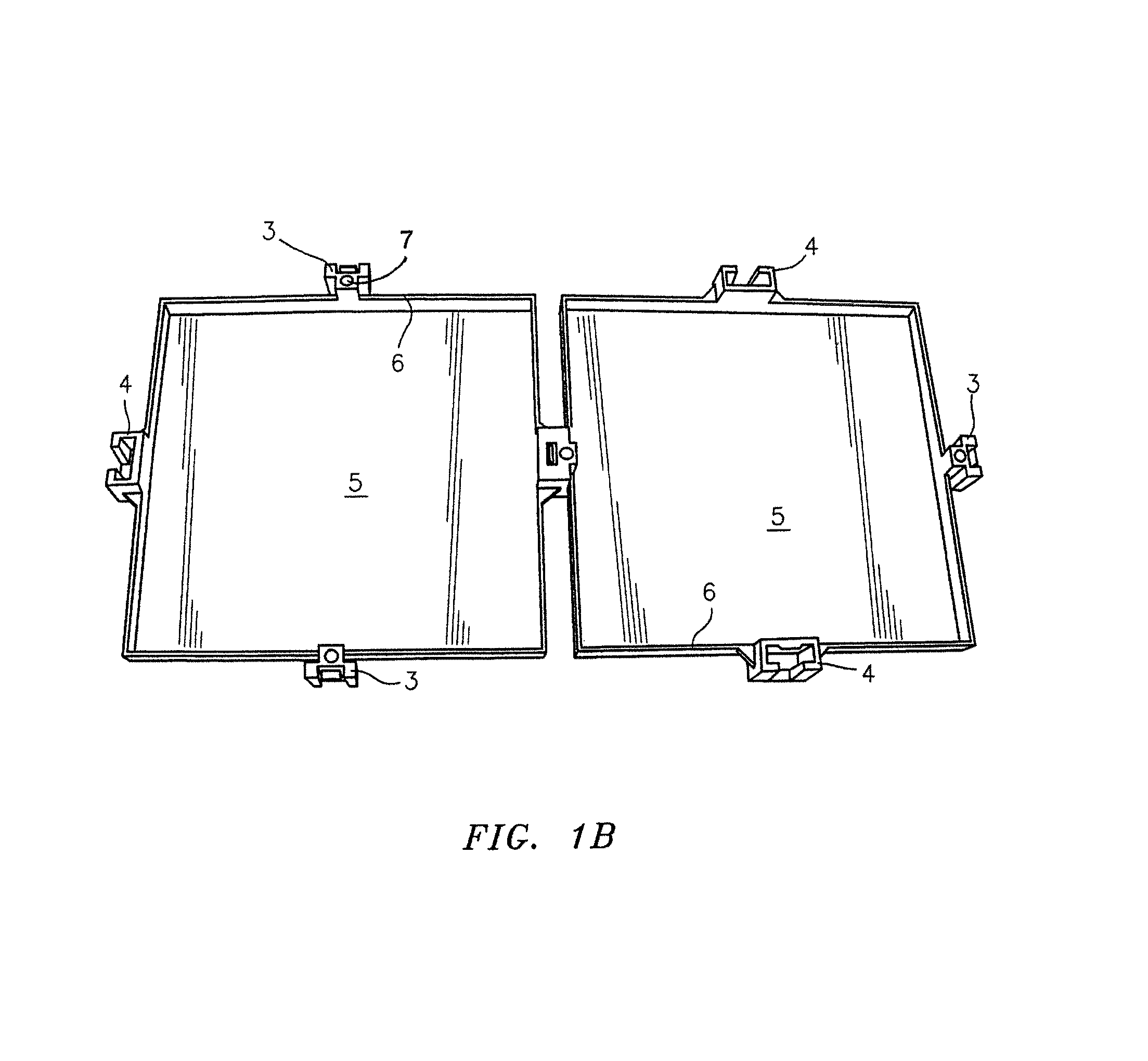
[0010]In view of the above-described problems, needs, and goals, it is an objective of the present invention to provide a solar concentrator of relatively simple construction which is inexpensive to manufacture and deploy. In one embodiment this is accomplished by assembling a plurality of reflector panels, each of which has a reflective front surface, into a contoured two-dimensional arrangement capable of directing incident solar radiation to a reference region. The reflector panels are simple, lightweight, and robust, yet of excellent optical quality and are inexpensive to manufacture and deploy. According to one specific embodiment of the invention, the reflector panels have a front surface which is optically flat, being formed from a lightweight yet rigid material having a specularly reflective coating formed thereon.
[0012]In one embodiment the reflector panels are formed from a plastic or composite material which yields a finished product of excellent hardness, rigidity, and durability and which is compatible with the process used to impart reflectivity to the front surface. According to another embodiment of the invention, the reflector panels are formed from acronitrile-butadiene-styrene (ABS) resins. The reflector panels are manufactured by injection molding into a single-cavity mold. In yet another embodiment the reflector panels may be formed from a lightweight metal such as aluminum, titanium, or related metal alloys.
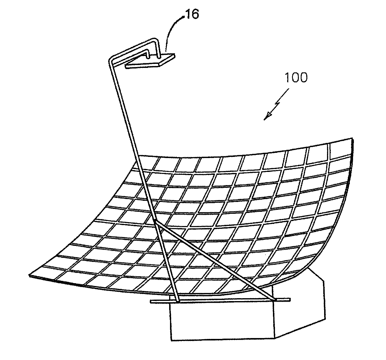
[0017]Another embodiment relates to a method of using a plurality of reflector panels to reflect and concentrate radiation to a region where it can be converted to a usable form of energy. This may be accomplished by the use of, for example a heat transfer medium, a photoelectric cell, a thermoelectric module, or a Stirling engine. When the solar concentrator is used to concentrate incident solar radiation onto the receiver, its efficiency can be maximized by tracking the sun's motion across the sky. By mounting the support frame assembly on dual rotable axes, the entire solar concentrator assembly can be rotated to continuously track the sun's motion across the sky and thereby maximize the intensity of solar radiation incident upon the receiver.

Problems solved by technology

Heliostats are disadvantageous in that they have stringent mirror contour requirements as well as the added expense of tall towers which are needed to support the remote receivers.
The disadvantages of troughs include a low maximum solar concentration, high receiver heat losses, and high receiver costs.
Since both heliostats and troughs do not face the sun directly, both suffer from performance losses known as cosine losses.
However, solar dishes are the most expensive solar reflectors, requiring fabrication of costly compound and complex reflector curves and the use of expensive mirror substrates.
Although the different types of solar mirrors discussed above may be advantageous for specific purposes, their complexity, stringent design requirements, and comparatively high cost are barriers to their widespread implementation as solar concentrators.
The additional cost considerations arise primarily from the complexity associated with their fabrication and use.
The complexity of conventional solar mirrors is furthered by the need for motorized solar tracking drives, tracking rails, and pivot bearings.
Although the above applications each address a number of design issues, the reflective surfaces used in the prior art still suffer from a number of problems.
These type of reflective surfaces are generally extremely heavy, are difficult to fabricate to precisely tailored dimensions and, in the case of glass, are susceptible to fracture.
An additional issue is that the materials from which the mirror itself is fabricated are generally expensive and are susceptible to corrosion under ambient conditions.

Method used


Image

  • Durable, lightweight, and efficient solar concentrator
  • Durable, lightweight, and efficient solar concentrator
  • Durable, lightweight, and efficient solar concentrator

Examples


Embodiment Construction

[0031]The above and other objectives of the invention will become more apparent from the following description and illustrative embodiments which are described in detail with reference to the accompanying drawings. Similar elements in each Figure are designated by like reference numbers and, hence, subsequent detailed descriptions thereof may be omitted for brevity.

[0032]The present invention relates generally to an improved solar concentrator, as presented in FIG. 5 (100). Incident radiation is reflected from a plurality of surfaces and concentrated upon a predetermined region where it is converted into a usable form of energy. As previously indicated, conventional solar concentrators suffer from a number of drawbacks arising primarily from their complexity and cost. The present invention is based on the discovery that many of these issues may be addressed by arranging a plurality of reflective panel front surfaces into a periodic arrangement having an overall shape analogous to a ...


PUM


Abstract

A solar concentrator, which is modular, durable, lightweight, and cost-efficient is described. The solar concentrator is constructed from a plurality of interconnected reflector panels that are secured to a contoured support frame assembly by means of an adjustable fastening mechanism. The reflector panels are preferably fabricated from a low-cost composite material and have an optically flat front surface. A specularly reflective front surface is formed on the reflector panel by deposition of a plurality of thin films which are highly reflective. Individual reflector panels can be interconnected and arranged into a two-dimensional grid having a predetermined degree of curvature by means of the contoured support frame assembly. Electromagnetic radiation incident upon the reflector panel arrangement is reflected to and concentrated upon a collector plate or receiving surface or receiver where it may be converted into a usable form of energy.

Description

CROSS-REFERENCE TO RELATED APPLICATIONS[0001]This application claims priority to U.S. Provisional Patent Application No. 61 / 132,490 which was filed on Jun. 19, 2008 and is incorporated by reference as if fully set forth herein.BACKGROUND OF THE INVENTION[0002]I. Field of the Invention[0003]This invention relates generally to a solar concentrator. In particular, the present invention relates to simple, lightweight, and inexpensive reflector panels comprising reflective surfaces of excellent optical quality. The invention also relates to an assembly comprising a plurality of reflector panels arranged on and secured to a contoured support frame assembly. The invention also relates to the use of this assembly to reflect and concentrate incident radiation onto a reference surface.[0004]II. Background of the Related Art[0005]A solar concentrator operates by intercepting incoming solar radiation and redirecting it to a concentrated region where it is changed into a useable form of energy t...

Claims


Application Information

Patent Timeline
Patent Type & Authority Patents(United States)
IPC IPC(8): F24J2/46F24J2/10F24J2/52H01L31/042F24J2/14F24J2/16F24S23/30F24S23/70F24S23/74F24S23/77
CPCF24J2/52F24J2/1057Y02E10/52F24J2/14F24J2002/467F24J2/16Y02E10/45Y02E10/47F24J2002/1085Y10T428/31504F24S23/74F24S23/77F24S23/82F24S25/00F24S2023/874F24S2025/6007Y02E10/40
Inventor SAPIENZA, RICHARD SABINOBAGNO, ROBERT
Owner PERSISTENT ENERGY
Why Eureka
Try Eureka