Inductance based parallel amplifier phase compensation

a phase compensation and parallel amplifier technology, applied in the direction of electric variable regulation, process and machine control, instruments, etc., can solve the problem of limiting the ability of parallel amplifiers to accurately regulate, and achieve the effect of reducing the output current, reducing the voltage of the first power supply output signal, and providing power more efficiently

Active Publication Date: 2014-11-04
QORVO US INC
View PDF240 Cites 42 Cited by
  • Summary
  • Abstract
  • Description
  • Claims
  • Application Information

AI Technical Summary

Benefits of technology

[0005]In one embodiment of the DC-DC converter, the parallel amplifier partially provides a first power supply output signal via the parallel amplifier output based on a voltage setpoint. The switching supply partially provides the first power supply output signal via the first inductive element and the second inductive element. The switching supply may provide power more efficiently than the parallel amplifier. However, the parallel amplifier may provide a voltage of the first power supply output signal more accurately than the switching supply. As such, in one embodiment of the DC-DC converter, the parallel amplifier regulates the voltage of the first power supply output signal based on the voltage setpoint of the first power supply output signal. Further, the switching supply regulates the first power supply output signal to minimize an output current from the parallel amplifier to maximize efficiency. In this regard, the parallel amplifier behaves like a voltage source and the switching supply behaves like a current source.
[0006]In o...

Problems solved by technology

At such frequencies, a group delay in the parallel amplifier may normally limit the ability o...

Method used


Image

  • Inductance based parallel amplifier phase compensation
  • Inductance based parallel amplifier phase compensation
  • Inductance based parallel amplifier phase compensation

Examples


Embodiment Construction

[0015]The embodiments set forth below represent the necessary information to enable those skilled in the art to practice the disclosure and illustrate the best mode of practicing the disclosure. Upon reading the following description in light of the accompanying drawings, those skilled in the art will understand the concepts of the disclosure and will recognize applications of these concepts not particularly addressed herein. It should be understood that these concepts and applications fall within the scope of the disclosure and the accompanying claims.

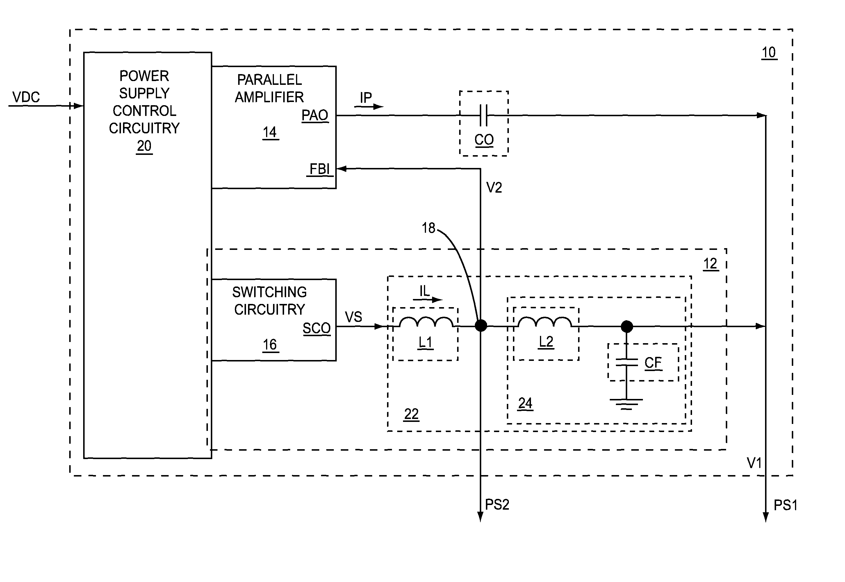
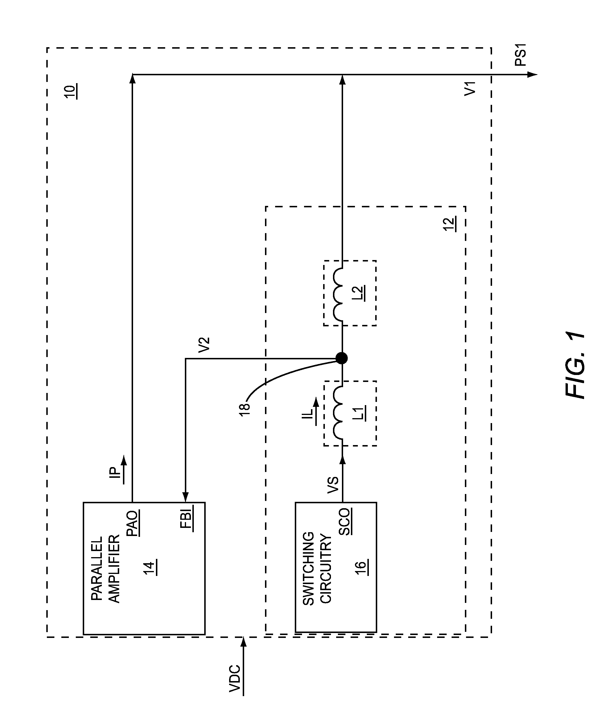
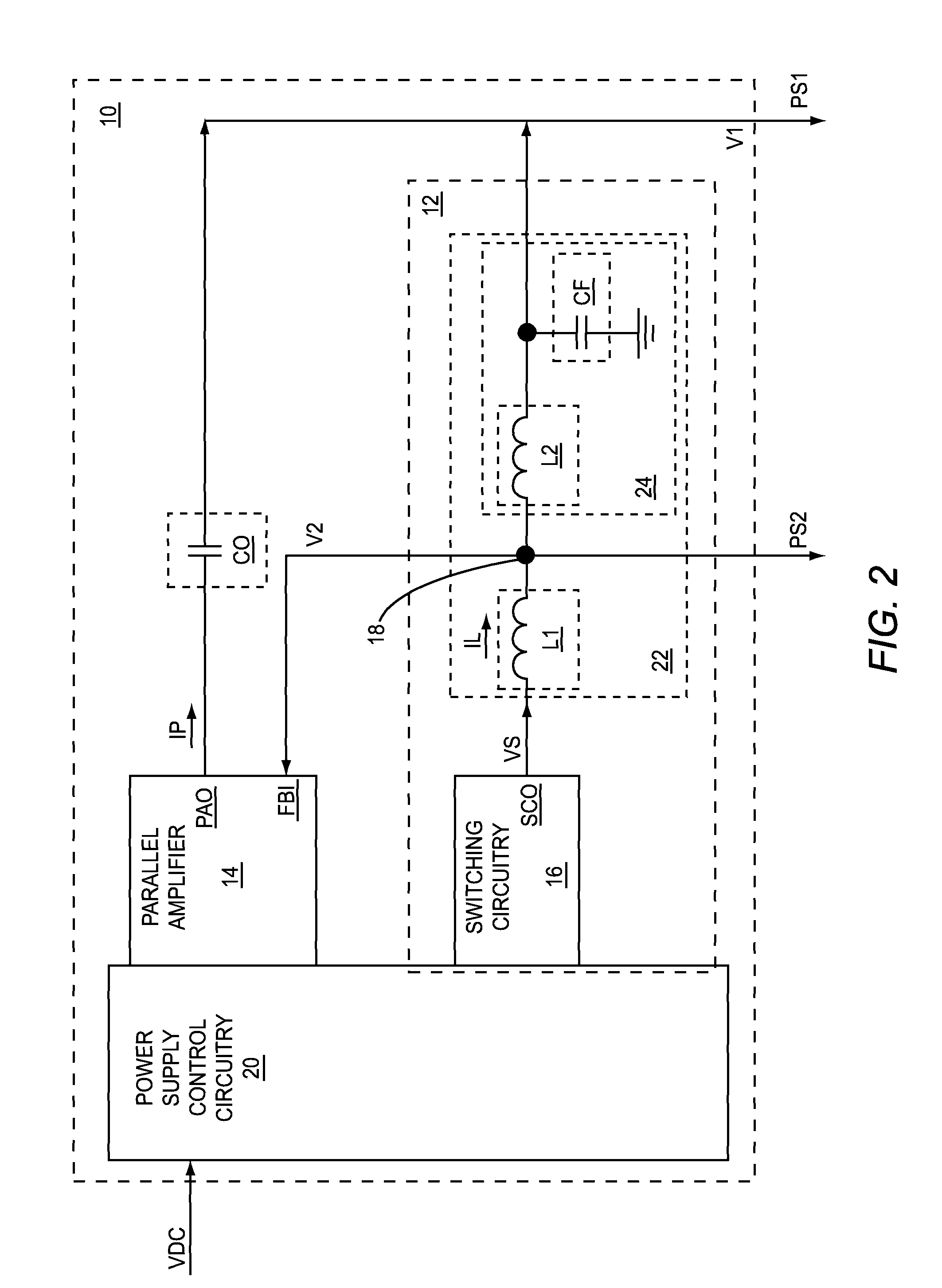
[0016]FIG. 1 shows a direct current (DC)-DC converter 10 according to one embodiment of the present disclosure. The DC-DC converter 10 includes a switching supply 12 and a parallel amplifier 14. The switching supply 12 includes switching circuitry 16, a first inductive element L1, and a second inductive element L2. The parallel amplifier 14 has a feedback input FBI and a parallel amplifier output PAO. The switching circuitry 16 has a ...


PUM


Abstract

A direct current (DC)-DC converter, which includes a parallel amplifier and a switching supply, is disclosed. The switching supply includes switching circuitry, a first inductive element, and a second inductive element. The parallel amplifier has a feedback input and a parallel amplifier output. The switching circuitry has a switching circuitry output. The first inductive element is coupled between the switching circuitry output and the feedback input. The second inductive element is coupled between the feedback input and the parallel amplifier output.

Description

RELATED APPLICATIONS[0001]This application claims the benefit of U.S. provisional patent application No. 61 / 551,596, filed Oct. 26, 2011, and U.S. provisional patent application No. 61 / 562,493, filed Nov. 22, 2011, the disclosures of which are incorporated herein by reference in their entireties.FIELD OF THE DISCLOSURE[0002]The present disclosure relates to direct current (DC)-DC converters and circuits that use DC-DC converters.BACKGROUND[0003]DC-DC converters often include switching power supplies, which may be based on switching at least one end of an energy storage element, such as an inductor, between a source of DC voltage and a ground. As a result, an output voltage from a DC-DC converter may have a ripple voltage resulting from the switching associated with the energy storage element. Typically, the ripple voltage is undesirable and is minimized as much as sizes and costs permit. Thus, there is a need to minimize ripple voltage using techniques that minimize sizes and costs....

Claims


Application Information

Patent Timeline
IPC IPC(8): H02M1/15H02M1/00H02M3/156H03G3/20
CPCH02M2001/0045H03F1/0216H03F3/2171H02M1/15H02M3/156H02M2001/0048Y02B70/1491Y02B70/10H02M1/0045H02M1/0048
Inventor KHLAT, NADIMKAY, MICHAEL R.GORISSE, PHILIPPE
Owner QORVO US INC
Why Eureka
Try Eureka