Raman signal detection and analysing system and a method thereof

a signal detection and analysis system technology, applied in the field of measuring instruments, can solve the problems of limited throughput, high system cost, limited throughput of single-detector systems, etc., and achieve the effects of reducing the cost of the raman detection system, increasing the measurement target/standard ratio, and improving the stability of the measuremen

Active Publication Date: 2014-11-04
HONG KONG APPLIED SCI & TECH RES INST
View PDF12 Cites 2 Cited by
  • Summary
  • Abstract
  • Description
  • Claims
  • Application Information

AI Technical Summary

Benefits of technology

[0004]In the light of the foregoing background, it is an object of the present invention to provide an alternative design of low-cost, high-throughput Raman signal detection and analyzing system.
[0010]With such an operation in modulation and demodulation of the two signals, the Raman detection with internal standard method can be implemented with weak signals. Another advantage of the present invention is that it only contains a single detector which significantly cut down the cost of the Raman detection system. Furthermore, the throughput of the present invention is higher and the measured target / standard ratio is more stable comparing with those in the conventional setup as there is no dispersive component, such as a grating. Last but not least, the simple signal decomposition algorithm enable the cost of the overall system to be further reduced.

Problems solved by technology

However, these systems are expensive and throughput is limited by the grating at required spectral resolution.
However, the throughput of such single-detector system is still limited by the use of grating.
Nonetheless, the costs of these new designs are not acceptable in constructing a home-used device for monitoring physiological parameters.

Method used


Image

  • Raman signal detection and analysing system and a method thereof
  • Raman signal detection and analysing system and a method thereof
  • Raman signal detection and analysing system and a method thereof

Examples


Embodiment Construction

[0018]As used herein and in the claims, “comprising” means including the following elements but not excluding others.

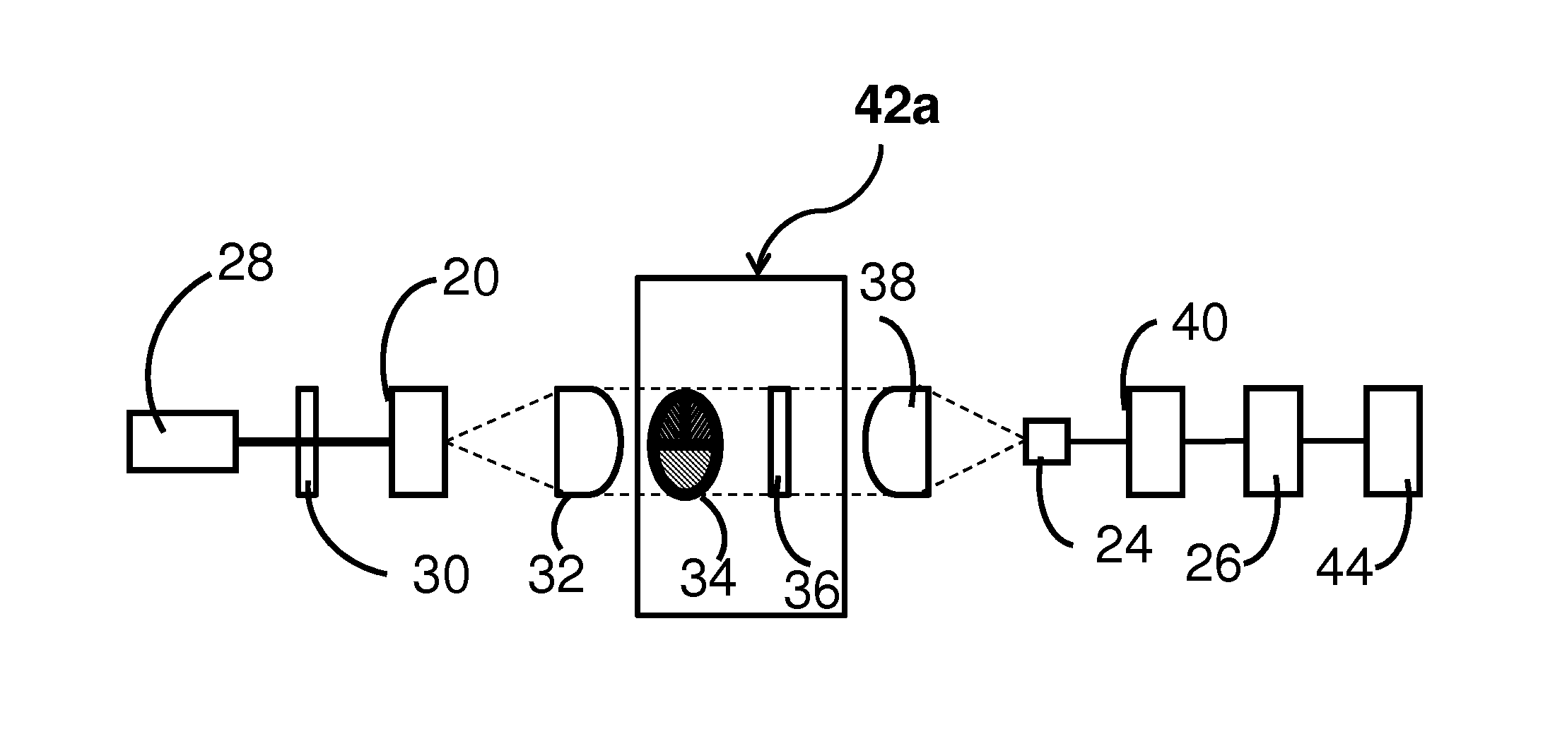
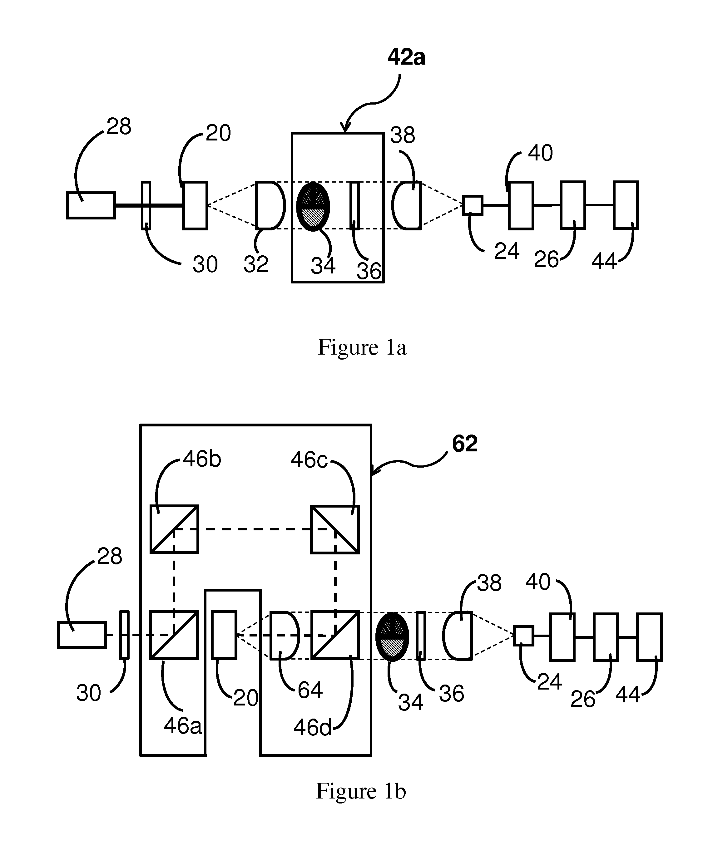
[0019]Referring now to FIG. 1a, an apparatus according to the present invention in post-filtering transmission mode is illustrated.

[0020]The system in transmission mode broadly includes an excitation light source 28, a laser line filter 30, a collimating lens 32, an optical module 42, a detector 24, a signal processing unit 40, a microprocessor 26 and a computer readable storage medium 44. The detector 24 is coupled to the signal processing unit 40, which is further coupled to the microprocessor 26. The computer readable storage medium 44 is coupled to the microprocessor 26.

[0021]The excitation light source 28 are configured to emit at least one excitation light at the excitation wavelength λE to a sample 20 to be measured after passing through one or two laser line filters 30. An optical signal, particularly, a Raman signal will be emitted from the sample 20 as a res...


PUM

PropertyMeasurementUnit
spectral wavelengthaaaaaaaaaa

Abstract

A Raman signal detection and analyzing system and a method thereof are disclosed. The Raman signal is generated by emitting an excitation light to a sample. The Raman signal is then modulated by passing through a plurality of optical filter and modulator. The resulting modulated Raman signal comprises two orthogonal components, which intensities are to be computed based on the first harmonic of said modulated Raman signal. The content of a specific analyte within the sample can then be determined based on the ratio of the intensities of the two components.

Description

FIELD OF INVENTION[0001]This invention relates to a measuring instrument and in particular a measuring instrument for detecting a content of an analyte in a sample by analyzing Raman signal with internal standard method.BACKGROUND OF INVENTION[0002]Raman spectroscopy is a powerful tool for quantitative analysis of the composition and concentration of a certain analyte within a sample. In the application of physiological detection, such an optical measurement is usually carried out in the near-infrared region. The Raman signal is often small, for instance the ratio of Raman signal strength to excitation signal strength is less than 10−10. Moreover the Raman signal is ultra-sensitive to the measurement conditions, such as laser fluctuation, optical bleaching, temperature variation, the changes in sample size and sample shape and optical alignment. Therefore internal standard method is usually applied during the analysis of the Raman signal. The basic principle of internal standard met...

Claims


Application Information

Patent Timeline
Patent Type & Authority Patents(United States)
IPC IPC(8): G01N21/65G01J3/44
CPCG01N21/65
Inventor KWOK, KA CHEUNGCHU, LUT HEYZHANG, CHUNLEUNG, LAP WAI LYDIA
Owner HONG KONG APPLIED SCI & TECH RES INST
Why Eureka
Try Eureka