Lighting device and method of making

a technology of light source and driver circuit, which is applied in the direction of discharge tube luminescnet screen, lighting and heating apparatus, light source combination, etc., can solve the problems of increasing increasing the cost of the fixture, and needing dim blue leds, so as to increase the complexity of the led driver circuit, reduce the ability to obtain dim blue leds, and improve the performance of blue leds

Active Publication Date: 2014-11-25
IDEAL IND LIGHTING LLC
View PDF81 Cites 15 Cited by
  • Summary
  • Abstract
  • Description
  • Claims
  • Application Information

AI Technical Summary

Benefits of technology

[0044]By replacing a BSY LED with a blue LED, a device is provided in which the same current that is provided in the BSY LEDs also passes through the longer wavelength blue LED. The blue LED can be brightness matched to the string current through the BSY LED to provide the correct amount of supplemental longer wavelength blue light to increase the CRI, but not so much as to move the color point outside the control range of the BSY and red string current controllers. This brightness matching results in very dim blue LEDs being needed to replace a BSY LED. As blue LED performance continues to increase, the ability to obtain dim blue LEDs is reduced.
[0045]An alternative to adding the longer wavelength blue LED into the BSY string is to provide separate control for the supplemental longer wavelength blue LED. This would require a separate current control for the supplemental blue LED which would increase the complexity of the LED driver circuit and increase the cost of the fixture.
[0194]By providing a long wavelength blue contribution as an excitation source of a phosphor converted LED, a same power supply topology as with a system with phosphor converted LEDs with a single wavelength excitation source can be employed. Such may be the case because the different phosphor converted LEDs can be from similar brightness bins. Additional blue light from the LW excitation source (i.e., the LW BSY LEDs) that would otherwise require a dim blue LED or a different drive current can be advantageously converted by the phosphor. Furthermore, because the additional LW blue is provided as a phosphor converted LED, the likelihood of a blue “hot spot” showing through a diffuser may be reduced. Thus, CRI may be maintained or improved even in the presence of shorter wavelength blue excitation sources.

Problems solved by technology

This brightness matching results in very dim blue LEDs being needed to replace a BSY LED.
This would require a separate current control for the supplemental blue LED which would increase the complexity of the LED driver circuit and increase the cost of the fixture.
Even if the design constraints of using a supplemental longer wavelength blue LED could be overcome, in some fixtures the inclusion of a blue LED may still create some adverse effects.
Thus, in some instances, replacing BSY LEDs with blue LEDs may not be an acceptable solution to improve the CRI of the LR24 or overcome changes in BSY excitation wavelength.

Method used


Image

  • Lighting device and method of making
  • Lighting device and method of making
  • Lighting device and method of making

Examples


example 1

[0399]A lighting device is constructed that has 9 BSY LEDs and 3 LWBSW LEDs, along with one or more red and / or orange LED.

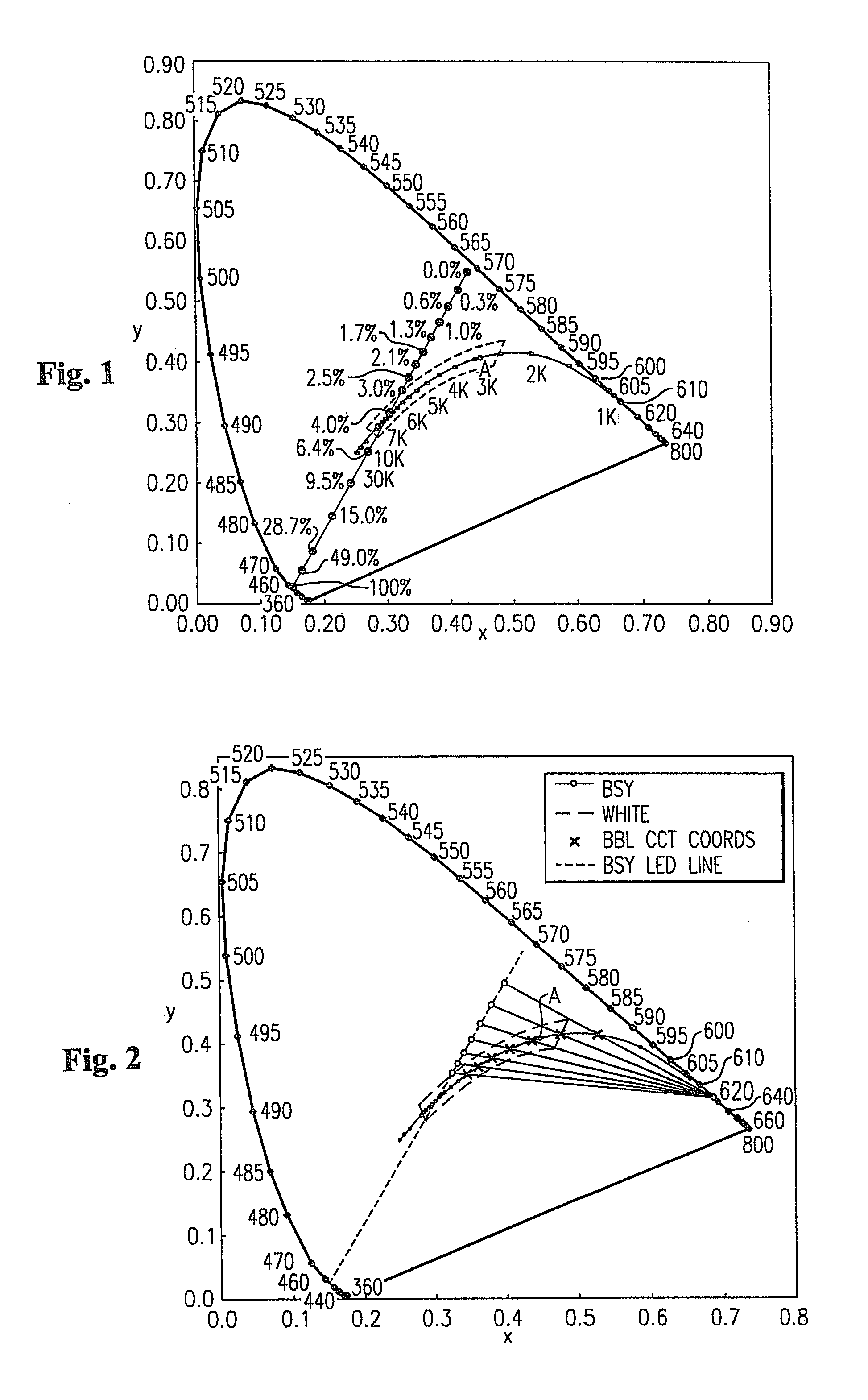
[0400]Each of the BSY LEDs emits light having x, y coordinates (1931 CIE Chromaticity Diagram) of 0.3545, 0.4053 (which correspond to u′, v′ coordinates (1976 CIE Chromaticity Diagram) of 0.1982, 0.5098), a dominant wavelength of 566 nm, a peak wavelength (i.e., wavelength of the blue / cyan / green LED excitation emitter) of 444 nm, a correlated color temperature of 4869 and a FWHM of 126.

[0401]Each of the LWBSY LEDs emits light having x, y coordinates of 0.3358, 0.4092 (which correspond to u′, v′ coordinates of 0.1856, 0.5088), a dominant wavelength of 556 nm, a peak wavelength (i.e., wavelength of the blue / cyan / green LED excitation emitter) of 472 nm, a correlated color temperature of 5414 and a FWHM of 113.

[0402]The red and / or orange LED(s) emits light having x, y coordinates of 0.6865, 0.3110 (which correspond to u′, v′ coordinates of 0.5143, 0.5227), a dominant...

example 2

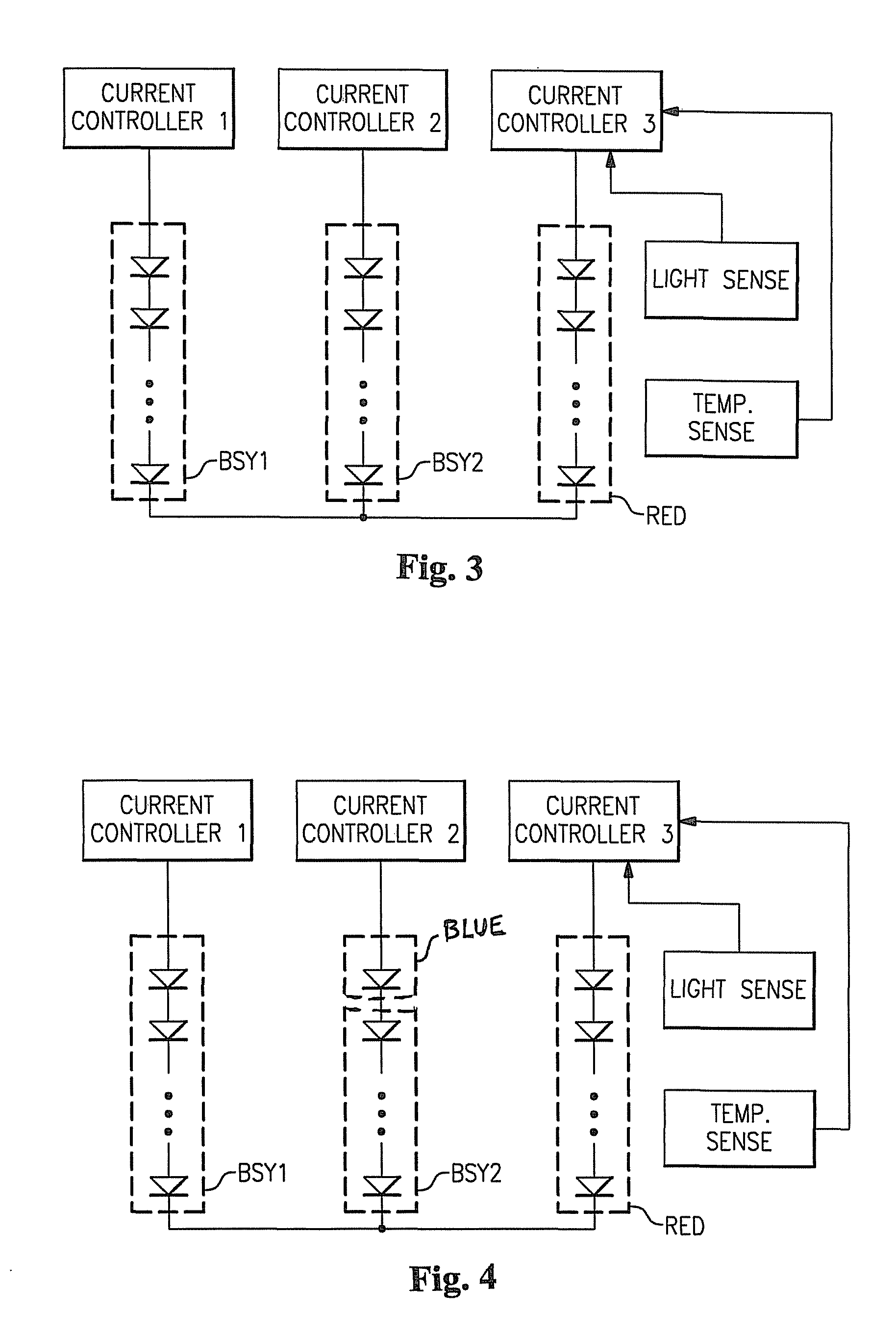
[0404]A lighting device is constructed that has two strings that each include six BSY LEDs, along with a third string that includes one or more red and / or orange LED.

[0405]Each of the BSY LEDs emits light having u′, v′ coordinates of 0.2362, 0.5121), a peak wavelength (i.e., wavelength of the blue / cyan / green LED excitation emitter) of about 450 nm, and a correlated color temperature of 3471.

[0406]Energy is supplied to the lighting device and the lighting device emits light that has a CRI Ra of 87.2.

[0407]One of the BSY LEDs in each of the BSY LED strings is then replaced with a LW BSY LED. Each of the LWBSY LEDs emits light having u′, v′ coordinates of 0.2358, 0.5112), a peak wavelength (i.e., wavelength of the blue / cyan / green LED excitation emitter) of 470 nm, and a correlated color temperature of 3468.

[0408]Energy is supplied to the lighting device and the lighting device emits light that has a CRI Ra of 93.7, and that includes about 14 lumen % from the red and / or orange LED(s), a...


PUM


Abstract

A lighting device comprising first and second groups of non-white light sources emitting light outside a first area on a 1976 CIE Chromaticity Diagram bounded by a curves 0.01 u′v′ above and below the blackbody locus and within a second area enclosed by saturated light curves from 430 to 465 nm and from 560 to 580 nm and segments from 465 to 560 nm and from 580 to 430 nm and a supplemental light emitter in the range of 600 to 640 nm. Also, a lighting device, comprising a first string of non-white phosphor converted light sources with excitation sources having dominant wavelengths that differ by at least 5 nm, a second string of non-white light sources, and a third string of supplemental light emitters in the range of 600 to 640 nm.

Description

CROSS-REFERENCE TO RELATED APPLICATIONS[0001]This application is related to U.S. patent application Ser. No. 12 / 720,387, filed Mar. 9, 2010 (now U.S. Patent Publication No. 2011-0221330), entitled “HIGH CRI LIGHTING DEVICE WITH ADDED LONG-WAVELENGTH BLUE COLOR” , the entirety of which is incorporated herein by reference.[0002]This application claims the benefit of U.S. Provisional Patent Application No. 61 / 334,390, filed May 13, 2010, the entirety of which is incorporated herein by reference as if set forth in its entirety.FIELD OF THE INVENTIVE SUBJECT MATTER[0003]The present inventive subject matter relates to lighting devices and methods of making them. In some embodiments, the present inventive subject matter relates to a lighting device which includes at least two non-white light sources and at least one supplemental light emitter which improve the CRI Ra of the light emitted from the lighting device. In addition, some embodiments of the present inventive subject matter provide...

Claims


Application Information

Patent Timeline
Patent Type & Authority Patents(United States)
IPC IPC(8): F21Y113/00F21V29/00H05B33/08F21Y101/02H01J1/62F21K99/00H05B44/00
CPCF21K9/137H05B33/0857F21Y2101/02H05B33/086F21Y2113/005F21V29/2206F21V29/74F21K9/233F21Y2115/10F21Y2113/13H05B45/20
Inventor NEGLEY, GERALD H.VAN DE VEN, ANTONY PAUL
Owner IDEAL IND LIGHTING LLC
Why Eureka
Try Eureka