Main bearing for crankshaft of internal combustion engine

a crankshaft and internal combustion engine technology, applied in the direction of crankshafts, sliding contact bearings, mechanical equipment, etc., can solve the problems of foreign matter, lubricating oil and foreign matter being difficult to be discharged from the lubricating oil groove of the main bearing, inducing damage to the slide surface,

Active Publication Date: 2014-12-09
DAIDO METAL CO LTD
View PDF19 Cites 11 Cited by
  • Summary
  • Abstract
  • Description
  • Claims
  • Application Information

AI Technical Summary

Benefits of technology

[0008]In the conventional main bearing in which the lubricating oil groove is formed in the inner circumferential surface throughout the entire length in the circumferential direction of the semi-cylindrical bearing, the lubricating oil which is supplied to the lubricating oil groove of the main bearing from the oil gallery in the cylinder block can flow to the end portion in the circumferential direction of the semi-cylindrical bearing, and therefore, the foreign matter accompanying the lubricating oil can be discharged to the outside of the bearing through a gap formed by the axial groove of the main bearing and the journal portion. However, in the case of the main bearing which is configured so that at least one of both end portions in the circumferential direction of the lubricating oil groove does not reach the axial groove, in order to reduce the leakage amount of the lubricating oil from the axial groove in response to miniaturization of the lubricating oil supplying oil pump as described above, not only the lubricating oil but also the foreign matter is difficult to be discharged from the lubricating oil groove of the main bearing, and tends to remain in the vicinity of the end portions in the circumferential direction of the lubricating oil groove.
[0009]The foreign matter which remains in the vicinity of the end portions in the circumferential direction of the lubricating oil groove becomes the cause of inducing damage to the slide surface between the journal portion and the main bearing. Further, the foreign matter enters the lubricating oil path in the inside of the crankshaft when the inlet opening of the first lubricating oil path formed on the outer circumferential surface of the journal portion passes the vicinity of the end portion of the lubricating oil groove, and is fed to the slide surface between the crankpin and the connecting rod bearing, where the foreign matter also becomes the cause of inducing damage. As a result, the main bearing which is configured so that at least one of both end portions in the circumferential direction of the lubricating oil groove does not reach the axial groove reduces the life of not only the main bearing itself but also the connecting rod bearing.
[0010]Accordingly, an object of the present invention is to provide a main bearing having an excellent foreign matter discharging function while reducing the leakage amount of oil, that is, a main bearing which can prevent a large number of foreign matters from remaining at an end portion in a circumferential direction of a lubricating oil groove while suppressing outflow of lubricating oil to an axial groove from the end portion in the circumferential direction of the lubricating oil groove formed in a bearing inner circumferential surface. Another object of the present invention is to provide a bearing device which is configured by such a main bearing and a journal portion.
[0030]By adopting the configuration of the present invention, the lubricating oil which is supplied into the lubricating oil groove through the through port formed in the wall of the main bearing is restrained from flowing out from the axial groove of the main bearing by a plurality of circumferential grooves formed on the extension portion of the inner circumferential surface that extends between the circumferential end portions of the oil groove and the axial groove, while the foreign matter accompanying the lubricating oil is guided from the oil groove to the axial groove by the steady flow of the oil flowing in the plurality of circumferential grooves so as to be properly discharged from the axial groove of the main bearing.

Problems solved by technology

The foreign matter is likely to damage a slide surface between the journal portion and the main bearing and a slide surface between the crankpin and the connecting rod bearing, and therefore, needs to be quickly discharged to the outside from the flow of the lubricating oil.
However, in the case of the main bearing which is configured so that at least one of both end portions in the circumferential direction of the lubricating oil groove does not reach the axial groove, in order to reduce the leakage amount of the lubricating oil from the axial groove in response to miniaturization of the lubricating oil supplying oil pump as described above, not only the lubricating oil but also the foreign matter is difficult to be discharged from the lubricating oil groove of the main bearing, and tends to remain in the vicinity of the end portions in the circumferential direction of the lubricating oil groove.
The foreign matter which remains in the vicinity of the end portions in the circumferential direction of the lubricating oil groove becomes the cause of inducing damage to the slide surface between the journal portion and the main bearing.
Further, the foreign matter enters the lubricating oil path in the inside of the crankshaft when the inlet opening of the first lubricating oil path formed on the outer circumferential surface of the journal portion passes the vicinity of the end portion of the lubricating oil groove, and is fed to the slide surface between the crankpin and the connecting rod bearing, where the foreign matter also becomes the cause of inducing damage.
As a result, the main bearing which is configured so that at least one of both end portions in the circumferential direction of the lubricating oil groove does not reach the axial groove reduces the life of not only the main bearing itself but also the connecting rod bearing.

Method used


Image

  • Main bearing for crankshaft of internal combustion engine
  • Main bearing for crankshaft of internal combustion engine
  • Main bearing for crankshaft of internal combustion engine

Examples


embodiment 1

[0057]Hereinafter, an embodiment of the present invention will be described with reference to the accompanying drawing.

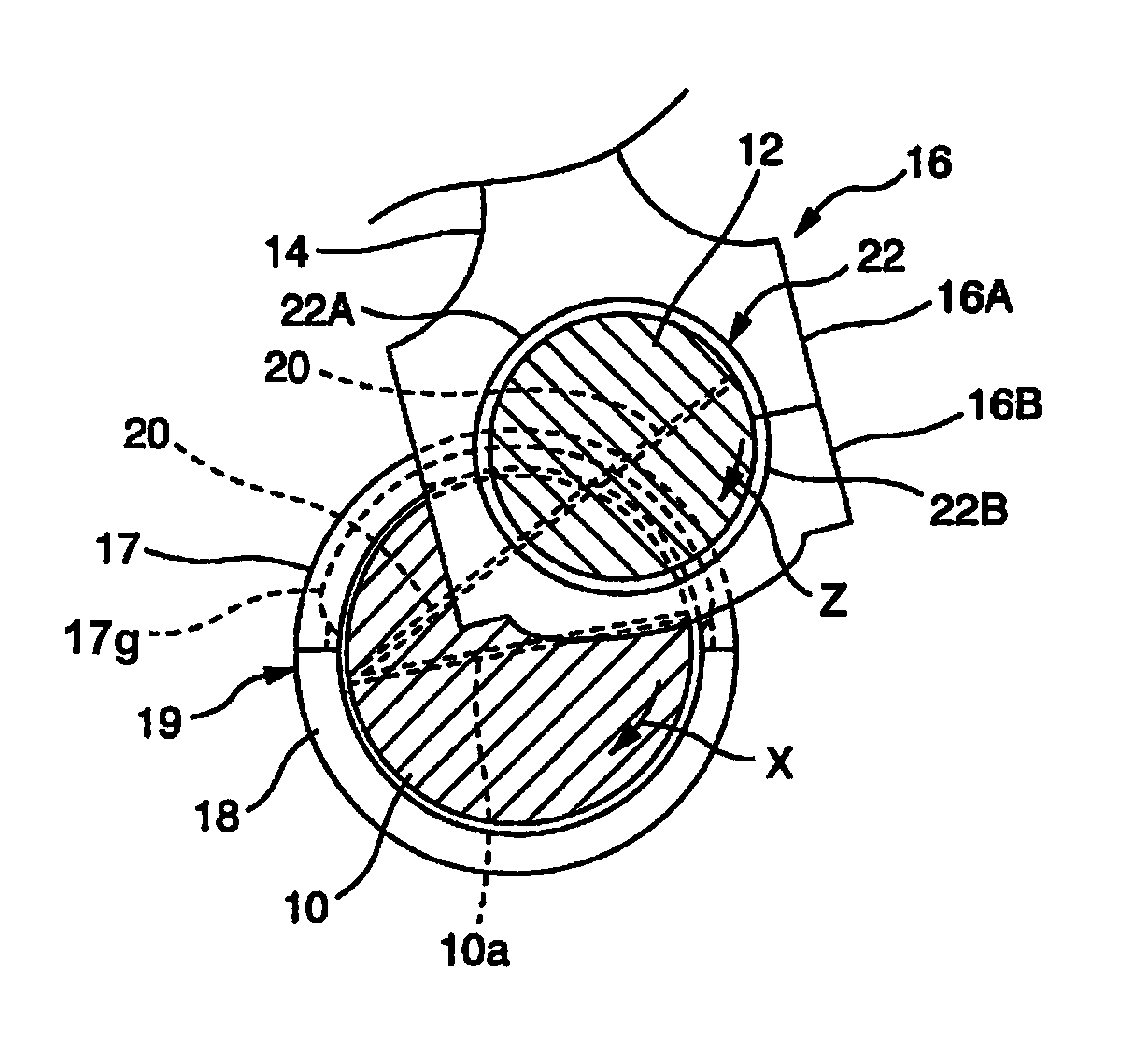
[0058]FIG. 1 is a schematic view of a crankshaft of an internal combustion engine cut at a journal portion and a crankpin section respectively, and shows a journal portion 10, a crankpin 12 and a connecting rod 14. As a positional relationship of the three members in a paper surface depth direction, the journal portion 10 is at a back side of the paper surface, the crankpin 12 is at a front side, and the crankpin 12 is enveloped by a large end portion housing 16 of the connecting rod 14 which carries a piston at the other end.

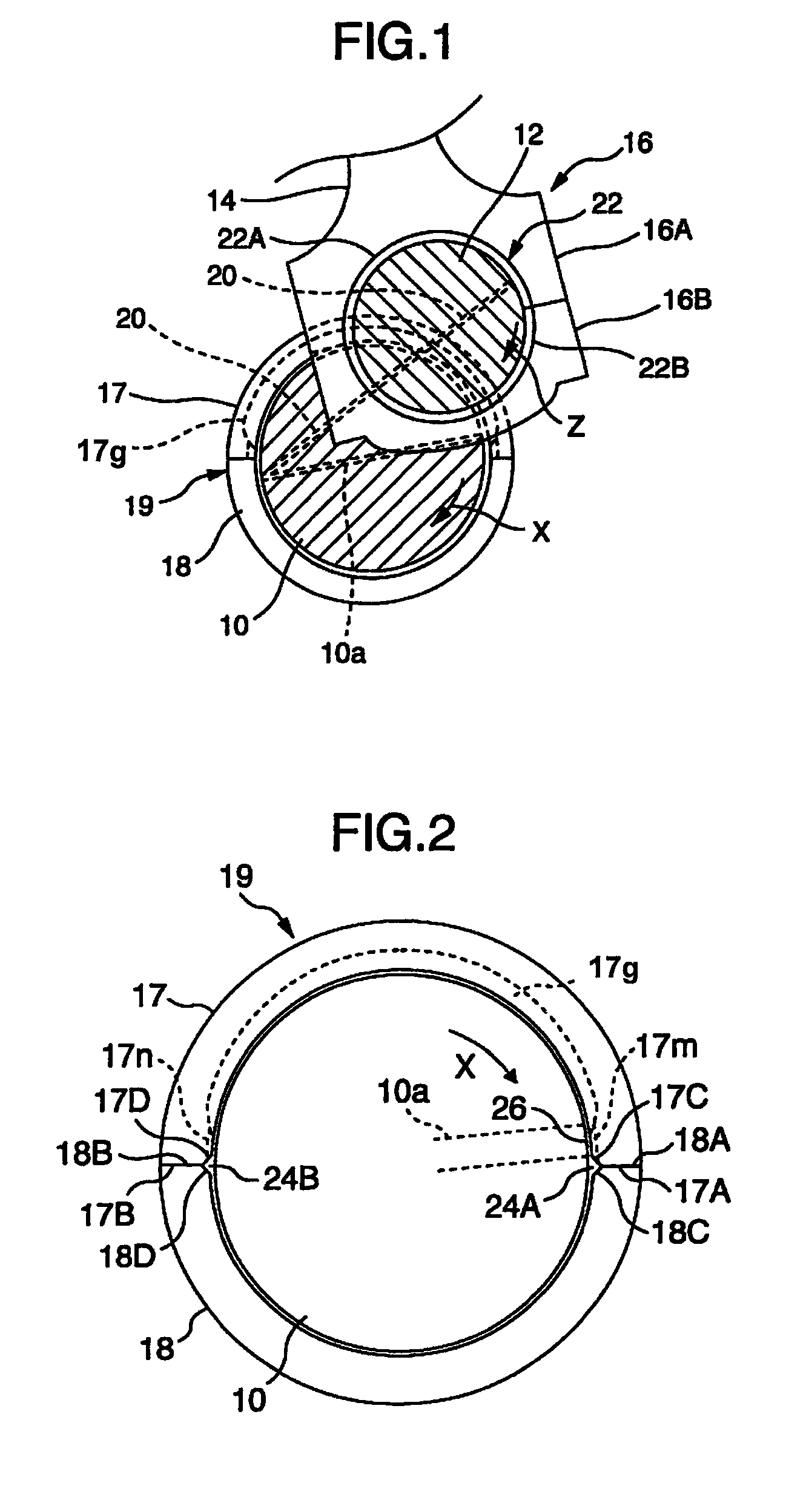
[0059]The journal portion 10 is supported in a cylinder block lower portion (not illustrated) of the internal combustion engine via a main bearing 19 which is configured by a pair of semi-cylindrical bearings 17 and 18. An oil groove 17q which extends in a circumferential direction except for regions near both ends of the main bearing is formed...

embodiment 2

[0086]FIG. 22 shows a crankshaft main bearing 19′ according to embodiment 2 of the present invention. As is understood from the drawing, the circumferential grooves 17m are formed between the oil groove 17g of a semi-cylindrical bearing 17′ and the axial groove 24A similarly to embodiment 1. However, when the circumferential groove 17m is formed by cutting after the semi-cylindrical bearing is formed, the circumferential grooves 17m can be produced more easily by forming the same circumferential grooves 17m also on the inner circumferential surface of the semi-cylindrical bearing at the same time, and therefore, in the present embodiment, the circumferential grooves 17m are formed also on the inner circumferential surface 17S other than the extension portion 17S′ between the oil groove 17g of the semi-cylindrical bearing 17′ and the axial groove 24A. As long as the circumferential grooves 17m according to the present invention are formed between the oil groove 17g and the axial groo...

embodiment 3

[0089]FIG. 24 shows a crankshaft main bearing 119 according to embodiment 3 of the present invention. As is understood from the drawing, an axial groove is formed only in a joint portion on the right side of the paper surface, among joint portions of semi-cylindrical bearings 117 and 118, and an oil groove 117a which is formed in the semi-cylindrical bearing 117 on the upper side of the paper surface has the configuration of the present invention described above only on a front side in the rotational direction of the journal portion. Namely, the oil groove 117a has a depth decreased gradually toward an end portion on the front side in the rotational direction, and thereby, an extension portion of an inner circumferential surface and a circumferential groove 117m on the front side in the rotational direction. Meanwhile, the oil groove 117a keeps a constant depth from the region including the center portion in the circumferential direction to the end portion on the rear side in the ro...


PUM


Abstract

A main bearing for a crankshaft of an internal combustion engine is composed of a pair of semi-cylindrical bearings. An oil groove extending in a circumferential direction is formed on an inner circumferential surface of one semi-cylindrical bearing. The oil groove has the depth gradually decreasing toward a circumferential end surface of the one semi-cylindrical bearing, and defines a circumferential end portion on the circumferential surface without extending to an axial groove formed in a joint portion of the pair of semi-cylindrical bearings. An extension portion of the inner circumferential surface extends between the circumferential end portion and the axial groove, and a plurality of circumferential grooves extending in the circumferential direction is formed on the extension portion from the oil groove to the axial groove over an entire width of the circumferential end portion of the oil groove.

Description

BACKGROUND OF THE INVENTION[0001](1) Field of the Invention[0002]The present invention relates to a main bearing for a crankshaft of an internal combustion engine, and more particularly relates to a main bearing for supporting a journal portion of a crankshaft in a cylinder block lower portion of an internal combustion engine. Further, the present invention also relates to a bearing device which is configured by such a main bearing and a shaft section corresponding thereto.[0003](2) Description of Related Art[0004]A crankshaft of an internal combustion engine is supported at a journal portion thereof in a cylinder block lower portion of the internal combustion engine via a main bearing formed by a pair of semi-cylindrical bearings. In order to lubricate the main bearing, lubricating oil pumped by an oil pump is fed through an oil gallery which is formed in a wall of the cylinder block and a through port which is formed in a wall of the main bearing into a lubricating oil groove whic...

Claims


Application Information

Patent Timeline
Patent Type & Authority Patents(United States)
IPC IPC(8): F16C9/02F16C33/10F16C17/02F16C33/04
CPCF16C33/1065F16C9/02F16C33/046F16C17/022F16C2360/22F16C3/14F16C17/02F16C33/10
Inventor ISHIGO, OSAMUTOMITA, YUICHIYAMADA, MOTOHIRA
Owner DAIDO METAL CO LTD
Why Eureka
Try Eureka