Eureka AIR delivers breakthrough ideas for toughest innovation challenges, trusted by R&D personnel around the world.

Fluid delivery system and method for monitoring fluid delivery system

a fluid delivery system and fluid technology, applied in the direction of heart stimulators, prostheses, therapy, etc., can solve the problems of human heart damage or dysfunction, heart failure, known conditions, etc., and achieve the effect of reducing the risk of heart failur

Active Publication Date: 2014-12-09
TC1 LLC
View PDF134 Cites 10 Cited by
  • Summary
  • Abstract
  • Description
  • Claims
  • Application Information

AI Technical Summary

Benefits of technology

[0012]The present application discloses a method for monitoring system performance, which can differentiate the effects of other physiological conditions. This method does not require the use of flow meters or pressure transducers. In fact, the method may not require any additional hardware to be added to the pump system. This allows the method to be easily and inexpensively implemented in new blood pump systems and to be readily retrofitted in existing blood pump systems, without compromising the systems' performance, reliability, and usability.
[0016]In aspects directed to the system, the pump event is one or a combination of events selected from the group consisting of occlusion, additional friction within the blood pump, thrombosis within the blood pump, kink in a graft or artificial conduit attached to the blood pump, increased drag on a rotor of the blood pump, increased drag on an impeller of the blood pump, and increased drag on an internal bearing of the blood pump.
[0030]In aspects directed to the method, the pump event is selected from the group consisting of occlusion, additional friction, thrombosis, kink in a graft or artificial conduit attached to the blood pump, increased drag on a rotor of the blood pump, increased drag on an impeller of the blood pump, increased drag on an internal bearing of the blood pump, and combinations thereof.
[0033]In aspects directed to the method, the determining step includes matching an operating condition of the blood pump to a specific pump event from a plurality of pump events including occlusion, additional friction, thrombosis, kink in a graft or artificial conduit attached to the blood pump, increased drag on a rotor of the blood pump, increased drag on an impeller of the blood pump, increased drag on an internal bearing of the blood pump, and combinations thereof.

Problems solved by technology

The human heart can become damaged or dysfunctional over time.
When damage to the heart becomes sufficiently serious, the heart fails to pump and circulate blood normally, resulting in a condition known as heart failure.
However, there is a shortage of donor hearts.
In a diseased state, one or both of the ventricles of the heart can become greatly weakened to an extent that mechanical intervention is needed to keep a patient alive.
Although either of the ventricles of the heart may function in a weakened state, failure of the left ventricle is more common.
These pulsatile ventricular assist devices are large and can only be used as an implantable treatment option for patients with a large body surface area.
One problem that can occur with a blood pump is that thrombus forms in the pump or is ingested, causing pump occlusion.
Pump occlusion can create a number of problems.
For example, pump occlusion can restrict blood flow through the pump, causing blood flow errors and disruptive blood flow conditions.
Furthermore, pump occlusion causes resistive forces that reduce the pump system's overall efficiency.
To differentiate between pump occlusion and patient's physiological conditions may be difficult and often requires the use of echocardiography.
However, flow meters and pressure transducers add to the complexity, size and cost of the blood pump system, and also add complexity to the surgical procedure for implanting the blood pump system.
In addition, flow meters and pressure transducers could be encapsulated or coated with biological materials and tissues can grow onto the sensing surfaces, rendering the flow meters and pressure transducers unfit for long-term use.
Another problem associated with pump thrombus is that it makes estimating pump flow rate more difficult and less accurate.
However, these methods are not reliable when thrombus forms in a blood pump.
In summary, available methods for monitoring pump occlusion are complex, large, costly, and in some cases unreliable.

Method used


Image

  • Fluid delivery system and method for monitoring fluid delivery system
  • Fluid delivery system and method for monitoring fluid delivery system
  • Fluid delivery system and method for monitoring fluid delivery system

Examples


Embodiment Construction

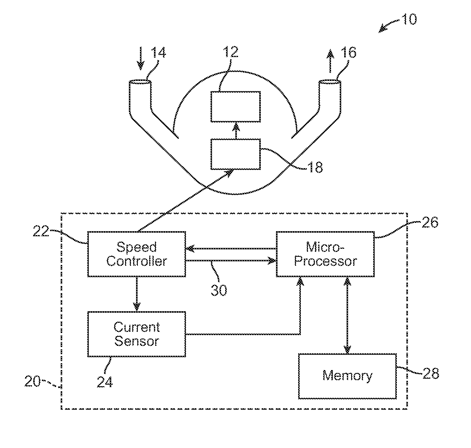
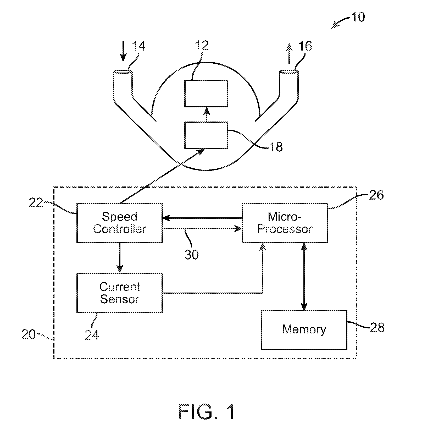
[0059]FIG. 1 shows a schematic diagram of a ventricular assist device 10 according to a preferred embodiment of the present invention. Although the ventricular assist device 10 is used to illustrate the present invention, the invention can be used with any suitable fluid delivery system. The device 10 includes an implantable pump 12 that can be connected to a patient's circulatory system. The pump 12 has an inlet 14 and an outlet 16. The pump can be an axial flow pump, a centrifugal pump, a positive displacement pump, or any other type of blood pump. The inlet 14 may connect to a conduit (not shown) that may in turn connect to a patient's circulatory system, such as at the left ventricle of the patient's heart. The outlet 16 may connect to another conduit (not shown) that may in turn connect to the patient's circulatory system downstream of the first conduit, such as in the aorta. The pump 12 can be implanted in the patient's abdomen, chest cavity, or in another location.

[0060]The v...


PUM


Abstract

A fluid delivery system includes an electric motor, a pump driven by the electric motor, and a control system. The control system is programmed to supply a variable voltage to the electric motor, to sense a response of a current of the electric motor to the variable voltage, and to obtain frequency domain information about the response of the current of the electric motor.

Description

CROSS-REFERENCE TO RELATED APPLICATION[0001]This application claims the benefit of U.S. Provisional Application No. 61 / 357,439, filed Jun. 22, 2010, which is incorporated herein by reference.FIELD OF THE INVENTION[0002]The present invention relates to a fluid delivery system and a method for monitoring a fluid delivery system, in particular a ventricular assist device. The present invention relates also to a method for computing the flow rate of a pump. The present invention relates further to a computer readable storage medium.BACKGROUND OF THE INVENTION[0003]Fluid delivery systems are widely used. An example of a fluid delivery system is a blood pump system. The human heart can become damaged or dysfunctional over time. When damage to the heart becomes sufficiently serious, the heart fails to pump and circulate blood normally, resulting in a condition known as heart failure. Around the world millions of people suffer from heart failure. Many people are unresponsive to pharmacologi...

Claims


Application Information

Patent Timeline
Patent Type & Authority Patents(United States)
IPC IPC(8): A61M1/10A61M1/12A61N1/362
CPCA61M2205/3365A61M1/1086A61M1/122A61M60/148A61M60/546A61M60/258A61M60/232A61M60/237A61M60/216A61M60/178A61M60/538A61M60/531A61M60/515A61M60/221
Inventor REICHENBACH, STEPHEN H.HSU, GEORGE CHAO-CHIHLAW, YU FAI
Owner TC1 LLC
Why Eureka
Eureka Blog
Learn More