Tumble dryer comprising a heat pump and heating system and method for operating the same

a technology of heat pump and heating system, which is applied in the direction of drying machines, lighting and heating apparatus, furnaces, etc., can solve the problems of not being able to use single-stage heaters with high heating power (e.g. 1800 w or more), and not being able to run a “fast program” using such dryers, and achieves rapid heating of process air and high heating power.

Inactive Publication Date: 2014-12-16
BSH BOSCH & SIEMENS HAUSGERAETE GMBH
View PDF16 Cites 16 Cited by
  • Summary
  • Abstract
  • Description
  • Claims
  • Application Information

AI Technical Summary

Benefits of technology

[0011]The object of the invention was hence to provide a tumble dryer comprising a heat pump, in which a conventional controller can also be used and an additional relay for the heat pump is not necessary. Preferably, in the dryer it shall also be possible to set a defined optimum working-fluid temperature easily.
[0026]In another preferred embodiment, the air-air heat exchanger can be removed. This is particularly advantageous because a removable heat exchanger can be cleaned more easily of lint.
[0030]During operation of the tumble dryer according to the invention, the refrigerant circuit is heated, for example in a drying process provided according to the invention as a standard operating mode (“standard program”; use of heater, air-air heat exchanger and heat pump). After reaching a temperature for tripping the thermostatic switch, for example the switching temperature Tmax, one of the two heating stages is switched off, preferably the heating stage having the higher heating power. The drying process then runs only using the one heating stage, i.e. one heating power. The refrigerant circuit is preferably designed here so that the heat pump does not go below the switching temperature Tmax again at the location of the temperature sensor. This results in rapid heating of the process air.
[0032]The invention has the advantage that a tumble dryer comprising a heat pump, a heater and an air-air heat exchanger can be operated very efficiently. A controller known for tumble dryers can be used here, so that there is no need to develop a new controller. Furthermore, the operation of the tumble dryer according to the invention involves fewer problems as regards the mains pollution associated with switching a heating stage having a high heating power.

Problems solved by technology

This removes a major disadvantage arising from the fact that the single-stage heater operating in parallel with the heat pump could only have a relatively low power, and hence it would not be possible using such a dryer to run a “fast program”, in which the drying would have proceeded without the aid of a heat pump.
A single-stage heater having a high heating power (e.g. of 1800 W or more), however, could not be used because of the numerous switching cycles required for operation using on-off switching to regulate the power and the resultant problems from mains pollution.

Method used


Image

  • Tumble dryer comprising a heat pump and heating system and method for operating the same
  • Tumble dryer comprising a heat pump and heating system and method for operating the same

Examples


Embodiment Construction

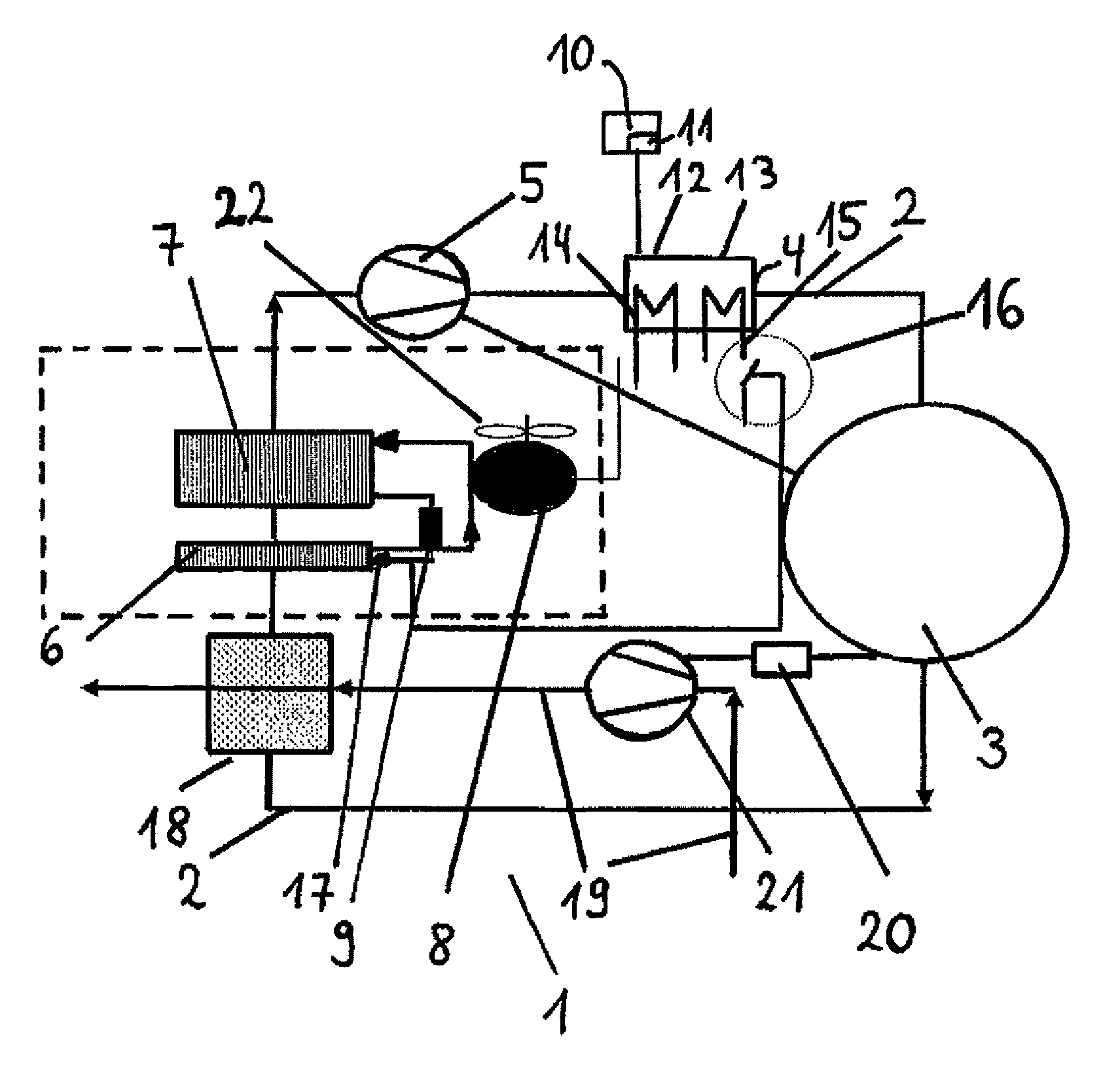
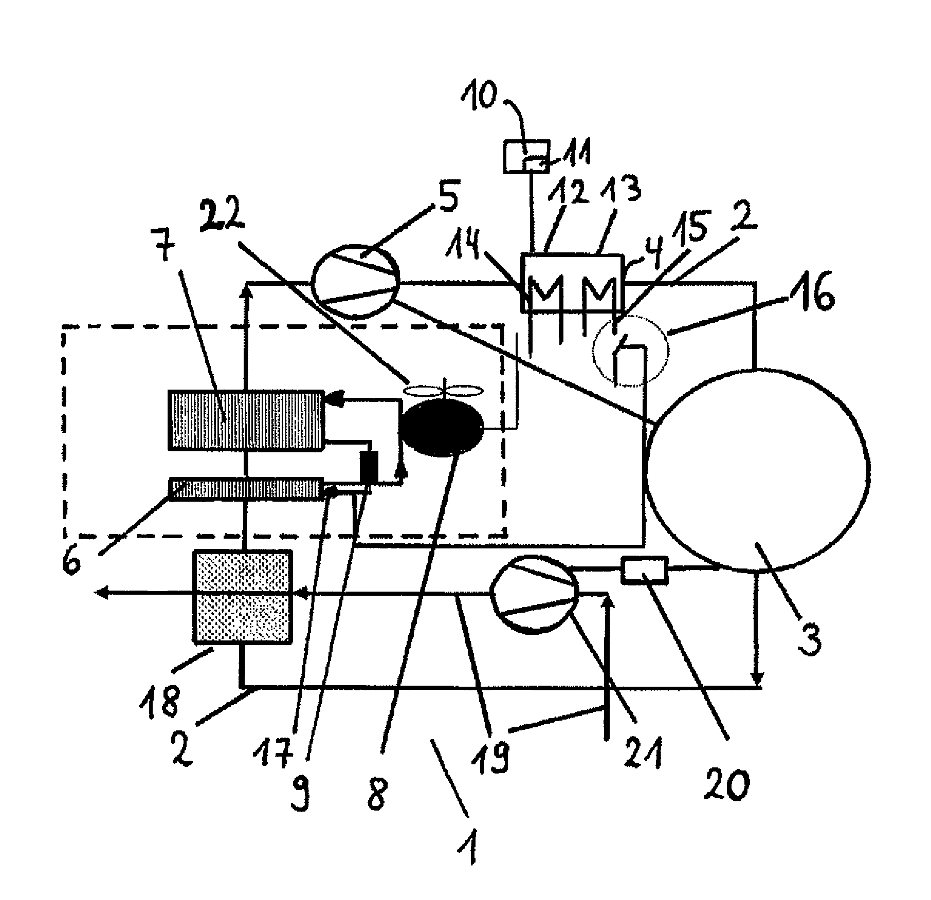
[0033]Further details of the invention follow from the description below of an exemplary embodiment, which is not restrictive, of the tumble dryer according to the invention and a method using this dryer. Reference is made to FIG. 1.

[0034]FIG. 1 shows a schematic diagram of a process-air circuit and a heat pump 6,7,8,9 for the tumble dryer 1, which here is in the form of a condenser dryer 1. In the dryer, process air is carried in a circuit of a heat transfer device 8,9 comprising the compressor 8 and the expansion valve 9. The process air is heated in the condenser 7 as the heat source 7 of the heat pump 6, 7, 8, 9 and conveyed by means of a first fan 5 to a heater 4 having a first heating stage 12 in a first circuit 14 and a second heating stage 13 in a circuit 15 parallel to the first, where it is heated further. The heated process air enters the drying chamber 3, where it can dry damp laundry (not shown here) by absorbing moisture. The moisture-laden warm process air then exits ...


PUM


Abstract

A tumble dryer having a drying chamber for articles to be dried; a process-air duct; a heater arranged to heat process air, wherein the heater is a two-stage heater having a first heating stage in a first circuit and a second heating stage in a second circuit that is parallel to the first circuit; a first fan to direct heated process air over the articles to be dried in the drying chamber; a heat pump having a heat sink, a heat source and a heat transfer device; a controller; and a thermostatic switch arranged in the first circuit or the second circuit, wherein the thermostatic switch is thermally coupled to the heat pump.

Description

BACKGROUND OF THE INVENTION[0001]The invention relates to a tumble dryer comprising a drying chamber for the articles to be dried, a process-air duct, in which is located a heater for heating the process air and in which the heated process air can be directed by a first fan over the articles to be dried in the drying chamber, and comprising a heat pump having a heat sink, a heat source and a heat transfer device, and also a controller, and relates to a preferred method for operating said tumble dryer.[0002]A conventional tumble dryer, whether or not it comprises a heat pump as a means of partial recovery of the thermal energy used to dry the washing that is provided, is designed either as a vented dryer or a condenser dryer.[0003]In the vented dryer, ambient air is drawn in from around the tumble drier, heated and conducted once over the washing to be dried for the purpose of absorbing moisture, and then ducted out of the tumble dryer. Since it is moisture-laden, the air cannot simp...

Claims


Application Information

Patent Timeline
Patent Type & Authority Patents(United States)
IPC IPC(8): D06F58/00F25B29/00D06F58/28F26B19/00D06F58/20F26B3/00D06F58/38
CPCD06F58/28D06F58/206D06F2058/287D06F2058/289D06F2103/50D06F2105/26D06F2105/28D06F58/38
Inventor STEFFENS, GUNTER
Owner BSH BOSCH & SIEMENS HAUSGERAETE GMBH
Why Eureka
Try Eureka