Support device for the gun sight of a military vehicle

a technology for supporting devices and military vehicles, which is applied in the direction of machine supports, shock absorbers, other domestic articles, etc., can solve the problems of device drawbacks, the strongest and most detrimental vertical vibratory stress, and the environment in which military vehicles equipped with a gun sight in a superstructure evolve, etc., to reduce the sensitivity to hysteresis phenomena

Active Publication Date: 2015-01-06
NEXTER SYST SA
View PDF17 Cites 0 Cited by
  • Summary
  • Abstract
  • Description
  • Claims
  • Application Information

AI Technical Summary

Benefits of technology

[0012]The invention proposes a support device for a gun sight able to provide suspension but reducing sensitivity to hysteresis phenomena whilst strongly absorbing the low frequency acceleration levels along the vertical axis and supplying a relatively rigid link between the gun sight and the vehicle in the horizontal plane.
[0013]According to one variant, the invention proposes means that also enable the damping of the system to be improved so as to reduce the amplitudes of the assembly and the time to return to equilibrium between two stresses.
[0014]Thus, the invention relates to a support device for the gun sight of a military vehicle, incorporating a head to which the gun sight is fastened and a foot which is integral with the vehicle, the head being integral with a column with a vertical axis which is introduced into the foot, the column being made integral with the foot by spring means, device wherein the spring means are constituted in the form of tongues arranged along at least two parallel planes perpendicular to the vertical axis of the support, each plane incorporating at least three tongues evenly spaced angularly around the column and integral with it by a first end and integral with the foot by their second end, these spring means imparting stiffness to the link between the column and the foot that is less along the vertical axis than along the other directions orthogonal to this vertical axis.
[0019]According to one embodiment, the tongues arranged on at least one of the planes may have a non-plane profile and will incorporate at least one wave enabling their tensile and compressive deformation capacity to be increased.

Problems solved by technology

The environment in which military vehicles equipped with a gun sight in a superstructure evolve often generates strong and intense vibrations due to travel and firing.
The vertical vibratory stresses are the strongest and the most detrimental to the durability of the electronic equipment forming part of modern a gun sight.
This device suffers from drawbacks, however.
The main drawback being that, in the case of a gun sight, the vibrations in the horizontal plane are such that a mounting that is not or is barely suspended is a requisite to contribute to firing accuracy.
However, shock isolators such as those disclosed in EP2146176 leave a considerable degree of freedom in the horizontal plane which perturbs aiming.
A second drawback linked to the device proposed in EP2146176 comes from the fact that the elastomers generate hysteresis phenomena and are highly sensitive to climatic elements.
Additionally, elastomers have a limited life and their properties evolve over time.

Method used


Image

  • Support device for the gun sight of a military vehicle
  • Support device for the gun sight of a military vehicle
  • Support device for the gun sight of a military vehicle

Examples


Embodiment Construction

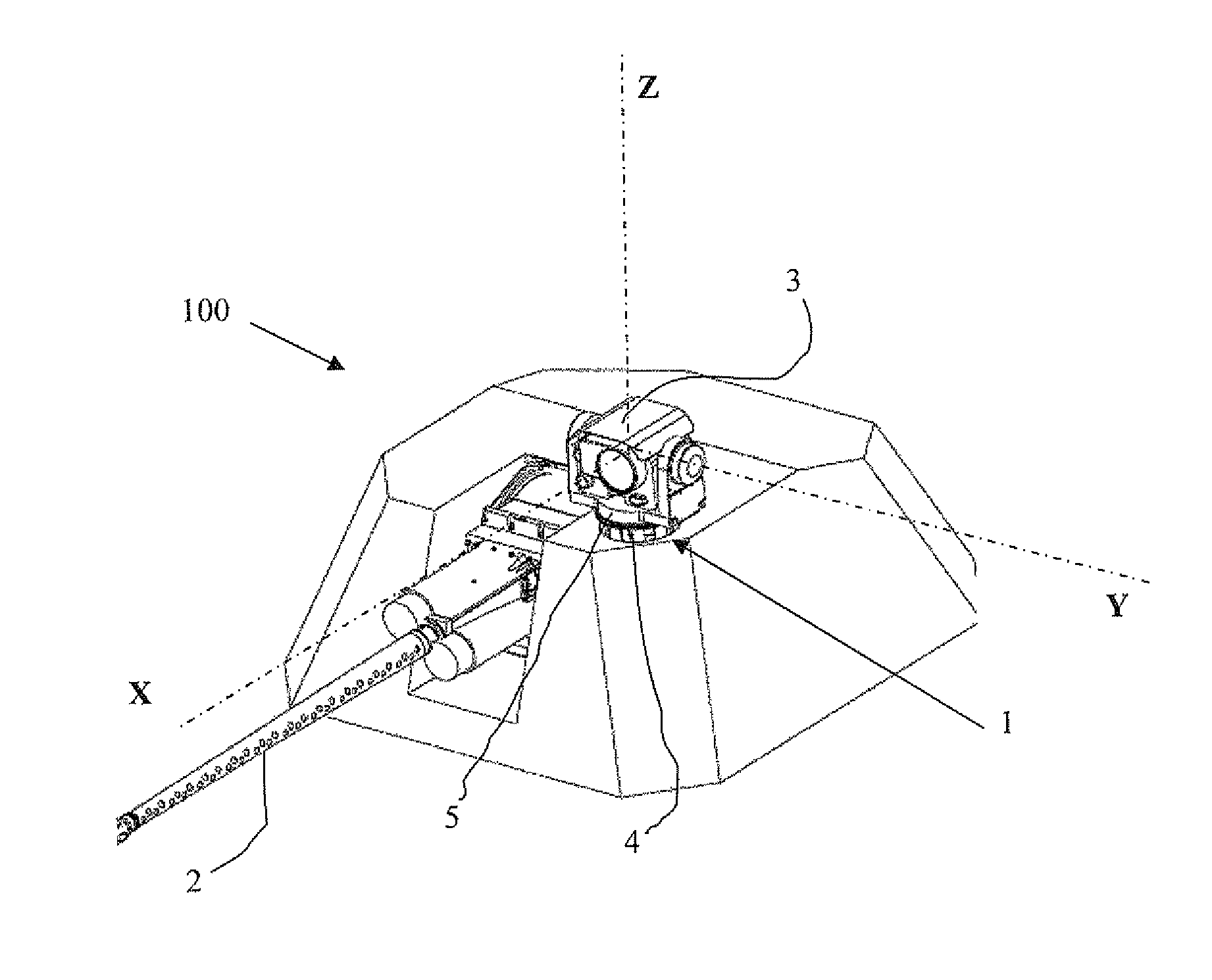
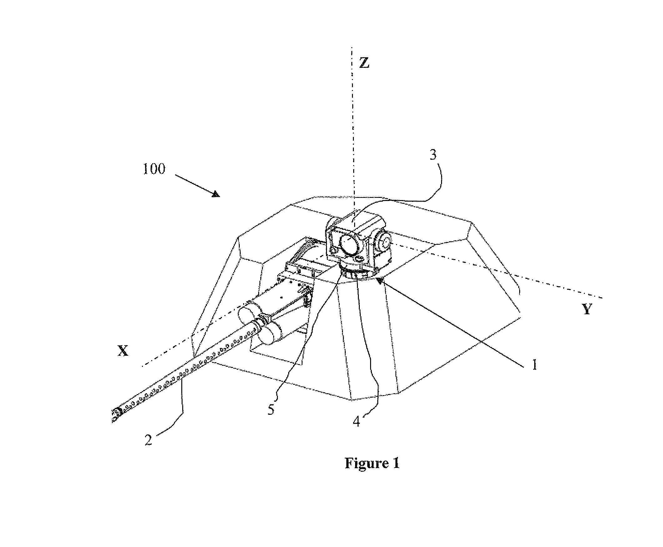
[0030]With reference to FIG. 1, a turret 100 of a military vehicle incorporates a support 1 for a gun sight, placed vertically in proximity to a gun 2. At the top of this support there is a gun sight 3. This gun sight is able to spin around three axes; roll (axis X), pitch (axis Y) and yaw (vertical axis Z). The support 1 incorporates two visible parts. A first tubular part with a substantially square section integral with the turret 100 by its lower part, designated support foot 4. A second cylindrical part, designed support head 5, integral with the gun sight.

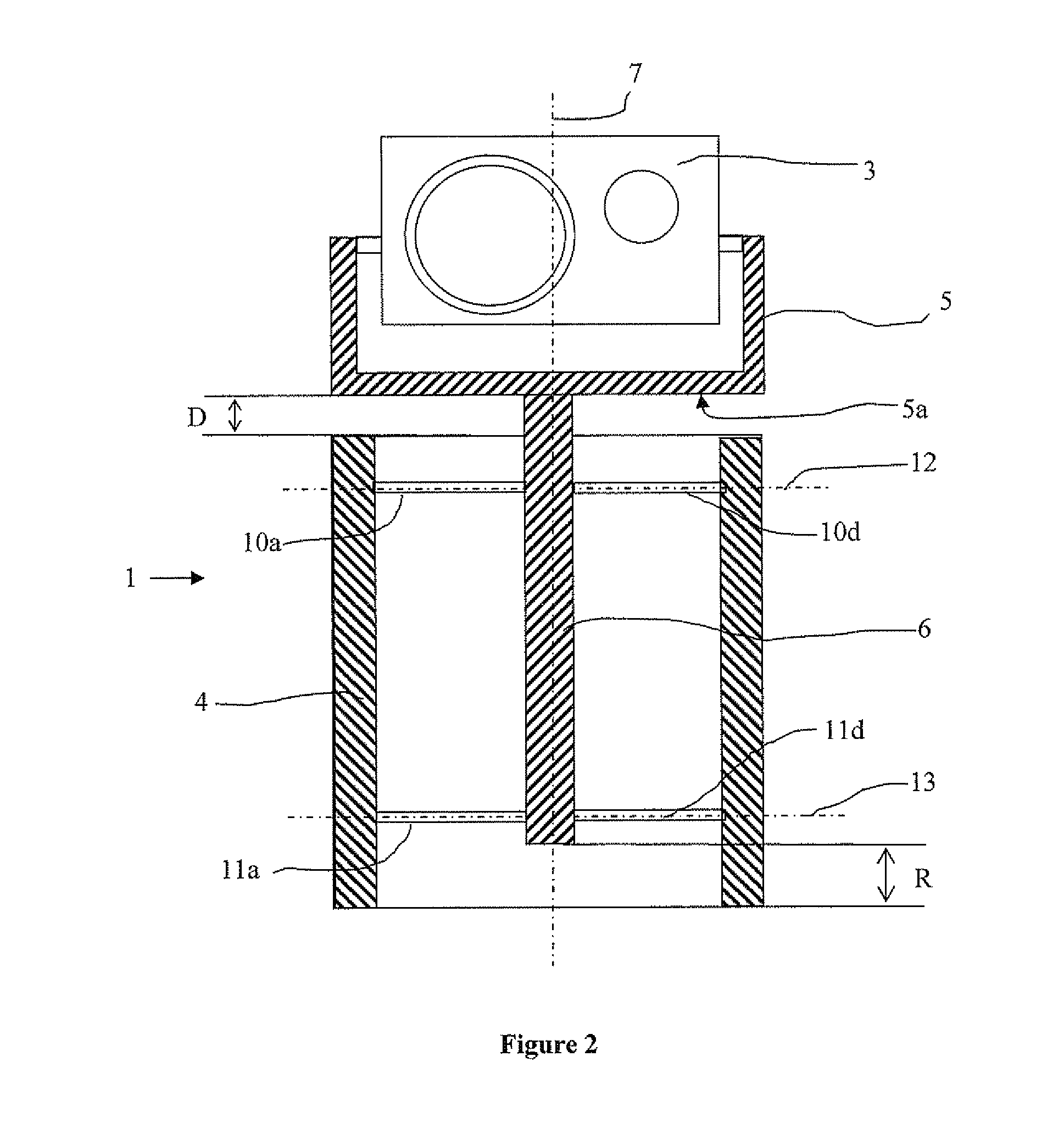
[0031]In the horizontal plane, the lower part of the head 5 is spaced from the upper part of the foot 4 by a distance D (see FIG. 2)

[0032]With reference to FIG. 2, the device 1 according to a first embodiment incorporates a column 6 integral with the lower part of the head 5 of the support 1 and perpendicular to a surface designated bottom 5a of the head 5. This column 6 is coaxial to the vertical axis 7 passing through the s...


PUM

PropertyMeasurementUnit
degrees of freedomaaaaaaaaaa
thicknessaaaaaaaaaa
shapeaaaaaaaaaa

Abstract

The invention relates to a support device for the gun sight of a military vehicle, incorporating a head to which the gun sight is fastened and a foot which is integral with the vehicle, the head being integral with a column with a vertical axis which is introduced into the foot, the column being made integral with the foot by spring means wherein the spring means are constituted in the form of tongues arranged along at least two parallel planes perpendicular to the vertical axis of the support, each plane incorporating at least three tongues evenly spaced angularly around the column and integral with it by a first end and integral with the foot by their second end, these spring means imparting stiffness to the link between the column and the foot that is less along the vertical axis than along the other directions (X, Y) orthogonal to this vertical axis.

Description

BACKGROUND OF THE INVENTION[0001]1. Field of the Invention[0002]The technical scope of the invention is that of supports for gun sights for military vehicles.[0003]2. Description of the Related Art[0004]On a military vehicle equipped with a gun sight, firing accuracy is due in part to the capacity of the sight to have a known fixed position on the vehicle. This is particularly true for boresighting, for example.[0005]The environment in which military vehicles equipped with a gun sight in a superstructure evolve often generates strong and intense vibrations due to travel and firing. The vertical vibratory stresses are the strongest and the most detrimental to the durability of the electronic equipment forming part of modern a gun sight.[0006]Thus, a person skilled in the art wishing to integrate such a sight onto a military vehicle must fulfill contradictory requirements of assembly rigidity to ensure accuracy and stability of aim on the one hand, and requirements of flexibility and ...

Claims


Application Information

Patent Timeline
Patent Type & Authority Patents(United States)
IPC IPC(8): F16M13/00F16F1/36F41A25/00F41G1/393F41G1/46
CPCF41G1/46F41G1/393
Inventor GERMENOT, OLIVIER
Owner NEXTER SYST SA
Why Eureka
Try Eureka