Cross-jack counterbalance system

a counterbalance system and cross-jack technology, applied in machines/engines, positive displacement liquid engines, borehole/well accessories, etc., can solve the problems of reducing the stroke length and the pump capacity, and reducing the overall work of pumping, so as to reduce maintenance costs, reduce energy consumption, and save lift costs

Inactive Publication Date: 2015-02-10
GUIDEMASTER MFG
View PDF20 Cites 8 Cited by
  • Summary
  • Abstract
  • Description
  • Claims
  • Application Information

AI Technical Summary

Benefits of technology

[0005]The current device provides a means to counterbalance the down-hole weights of a reciprocating pumping unit, while substantially eliminating ineffective horizontal translations of these weights, more efficiently offsetting the vertical translations of the down-hole weights with each stroke of the reciprocating pump unit. This substantially eliminates a significant portion of ineffective work associated with a conventionally balanced pumping unit. This reduces the overall work of pumping, energy consumption and thereby, lift costs. One of the core novelties and benefits of this device and methodology is derived from eliminating unnecessary horizontal translations of the counterbalance weights throughout the entire reciprocating stroke cycle of the pump unit. This applies to substantially all current reciprocating pump units. Moreover, this device and methodology does not preclude the use of the other efficiencies described above and does not require any modification or replacement of down-hole components.
[0006]The current embodiment represents an attachment and modification of a pre-existing cantilevered beam pumping unit, which uniquely suspends the counterweights as described above and changes the center of gravity as described below, both to reduce work required with each stroke cycle.
[0007]This system works with substantially all reciprocating pumps, requiring counterbalancing of down-hole weights across a cantilevered beam. Beam balanced pumps offer similar advantages in terms of reduced drive unit power; however, they suffer reduced stroke length and reduced pump capacity. Also, they become relatively unbalanced at larger angles of walking beam tilt. Therefore, they have been limited to use in relatively shallow wells. Because the only effective work in the reciprocating pump cycle involves the vertical up and down movement of the sucker rod, pump components and the corresponding counterbalanced weights on the other side of the walking beam pivot, any horizontal translation of the counterweights is ineffective work. In the common crank-balanced pump the rotation of the counterweights mounted on the crankshaft has a horizontal force vector in all but the twelve and six o'clock positions. Reducing this to horizontal and vertical vectors only, fifty percent (50%) of the work used to move the counterweights is horizontal, and thus ineffective. Because the drive unit directly effects counterweight movement and indirectly moves the rod-pump complex through the walking beam, only the vertical forces on the counterweights produce vertical movement on the down-hole pump components. Thus fifty percent (50%) of the power drive unit work can be ineffective in pump output. Frequency driving the primary mover unit differentially in different portions of the rotational cycle can reduce power consumption during less vertically efficient portions of the rotational stroke cycle. However, because the vertical and horizontal components cannot be completely isolated, the reduction of ineffective power consumption is limited.

Problems solved by technology

This reduces the overall work of pumping, energy consumption and thereby, lift costs.
Beam balanced pumps offer similar advantages in terms of reduced drive unit power; however, they suffer reduced stroke length and reduced pump capacity.
Also, they become relatively unbalanced at larger angles of walking beam tilt.
Therefore, they have been limited to use in relatively shallow wells.
Because the only effective work in the reciprocating pump cycle involves the vertical up and down movement of the sucker rod, pump components and the corresponding counterbalanced weights on the other side of the walking beam pivot, any horizontal translation of the counterweights is ineffective work.
Reducing this to horizontal and vertical vectors only, fifty percent (50%) of the work used to move the counterweights is horizontal, and thus ineffective.
Thus fifty percent (50%) of the power drive unit work can be ineffective in pump output.
However, because the vertical and horizontal components cannot be completely isolated, the reduction of ineffective power consumption is limited.
This can result in significant levels of wasted work, which can be eliminated with the current device.

Method used


Image

  • Cross-jack counterbalance system
  • Cross-jack counterbalance system
  • Cross-jack counterbalance system

Examples


Embodiment Construction

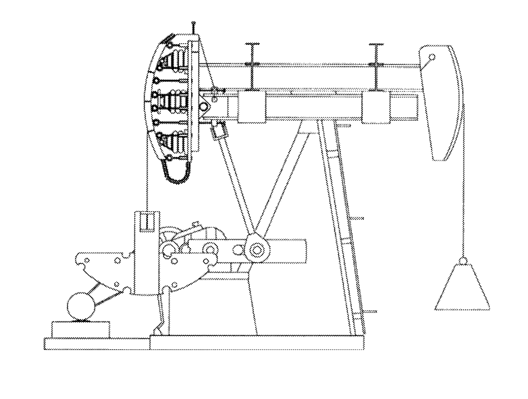
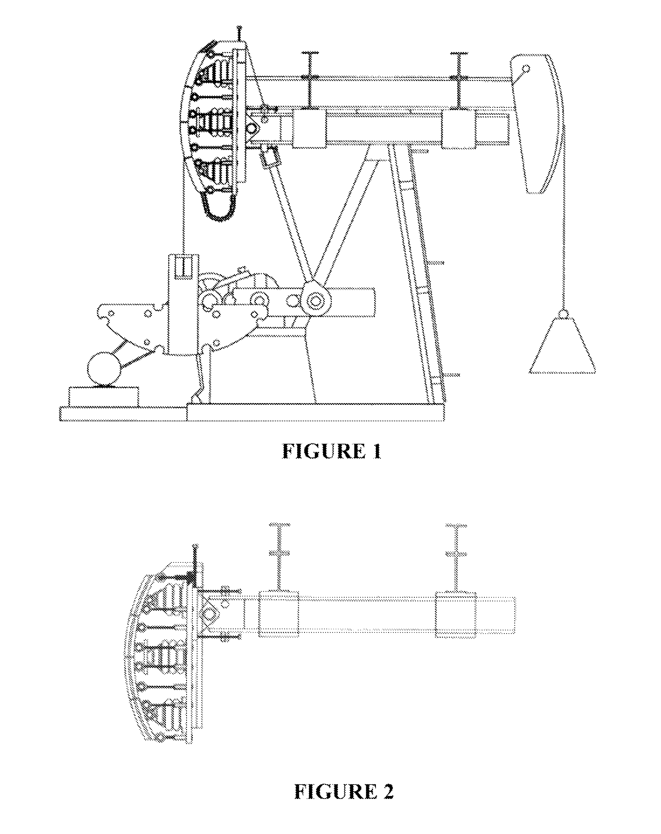
[0026]The device and method of implementation of the current art can be retro-fitted onto pre-existing pumping platforms as described above, or it can be the core concept for a new unique pumping unit that incorporates the components, methods and utility of the current art. The embodiment of the current device consists of attachable components which reduce the work performed by a reciprocating pumping unit whether the down-hole weights are beam balanced, crankshaft balanced or compound balanced by uniquely counterbalancing them in this non-obvious manner, which eliminates the wasted work of horizontal translation of said weights while simultaneously reducing or eliminating unwanted induced torque forces produced by the mal-alignment of the center of gravity of the walking beam complex and the center of pivot of said beam complex. The methodology of setup and implementation of the device of the current art accomplishes the following utility:

[0027]a) The device installs and operates i...


PUM


Abstract

The device is a counterbalance system and method to reduce the work of conventionally balanced, reciprocating cantilevered beam pumping units, and comprises a pair of transversely oriented support mounts attached to the cantilevered beam or walking beam of a pre-existing reciprocating pumping unit, attaching on either side of the pivoting-fulcrum, mounting point of the cantilevered walking beam. These transverse mounting points terminate individually on either side of said walking beam in channel-like saddles that support independent, parallel beams, which in turn cantilever themselves in tandem with said walking beam of the pumping unit; moreover, the position of the parallel beams by virtue of the transverse mounts creates a new center of gravity corresponding to the center of the pivoting mounting point of the walking beam, eliminating counter-productive torque forces on the walking beam as it tilts from horizontal.

Description

BACKGROUND OF THE INVENTIONField of the Invention[0001]The present invention relates in general to methods and apparatus for reducing the energy requirements for operation of an oil well pump jack or other reciprocating pumps with a unique counterbalance system, reducing operational work of the drive system.[0002]As a major component of oil and gas production, reciprocating pump jacks are a form of counterbalanced reciprocating pumps that lift oil in wells with insufficient bottom-hole pressure to lift reserve fluids to the surface. The most common of these pumps consist of an above ground drive unit that produces an effective reciprocating mechanical action from a rotating, counterbalanced crankshaft connected through a walking beam. The pump is positioned “down-hole” at an effective depth that draws directly from underground reserves. The reciprocating down-hole pump can be hundreds or even thousands of feet below the surface, contained within the well casing. The connection to th...

Claims


Application Information

Patent Timeline
Patent Type & Authority Patents(United States)
IPC IPC(8): E21B19/02F04B47/14
CPCF04B47/14Y10T74/2156Y10T74/18182E21B43/127
Inventor SMITH, ALAN D.
Owner GUIDEMASTER MFG
Why Eureka
Try Eureka