Superlattice crystal resonator and its usage as superlattice crystal filter

a superlattice crystal and filter technology, applied in piezoelectric/electrostrictive/magnetostrictive devices, piezoelectric/electrostriction/magnetostriction machines, electrical apparatus, etc., can solve the problems of surface acoustic wave resonators with drawbacks, low power handling capacity, and difficult processing, etc., to achieve high selectiveness, high power handling capacity, and insufficient power handling capacity

Inactive Publication Date: 2015-02-17
SHOULDER ELECTRONICS CO LTD
View PDF9 Cites 4 Cited by
  • Summary
  • Abstract
  • Description
  • Claims
  • Application Information

AI Technical Summary

Benefits of technology

[0006]In view of the drawbacks of the existing SAW resonator, SAW filter and dielectric filter, research has been conducted and an improvement has been made in the present invention to provide a superlattice crystal resonator with enhanced technical effects, and applications of such resonator as a superlattice crystal filter. The superlattice crystal resonator of the present invention is easy to process and has high power handling capacities, and the superlattice crystal filter has advantages of, such as, high power handling capacity, low insertion loss, small dimension, etc.
[0011]The superlattice crystal resonator of the present invention uses a dielectric acoustic superlattice crystal material as a substrate, and its resonance frequency is decided only by the vibration period of the superlattice itself and is independent of the thickness of the wafer. The thickness of the wafer may be selected according to actual processing capacity and skill. Therefore, it is possible to effectively solve problems in the prior art such as difficulty of processing a very thin wafer, insufficient power handling capacity, etc, which would occur when using an ordinary piezoelectric crystal to fabricate a high-frequency resonator.
[0012]The superlattice crystal filter of the present invention enjoys the combined advantages of an SAW filter and a dielectric filter. The filter fabricated by a substrate of a dielectric acoustic superlattice crystal material according to the present invention, in addition to the performance of an ordinary filter, has advantages of a high power handling capacity, high selectiveness (“squareness index”), low insertion loss, small dimension, low process cost, etc.

Problems solved by technology

The existing SAW (Surface Acoustic Wave) resonator has drawbacks because it has a low power handling capacity and is difficult to process when used for a high frequency situation.
However, as the existing SAW resonator has low power handling capacities, its application is limited when higher power handling capacities are necessary.
The existing dielectric filter, on the other hand, has characteristics of low insertion loss and high power handling capacities, but has poor bandwidth selectivity (or “squareness index”) and large dimensions so that the usefulness of the existing dielectric filter is rather limited when high selectivity is required.
If its selectivity is to be increased, the insertion loss and dimension will be increased as well, which in turn increases the cost of the application.

Method used


Image

  • Superlattice crystal resonator and its usage as superlattice crystal filter
  • Superlattice crystal resonator and its usage as superlattice crystal filter
  • Superlattice crystal resonator and its usage as superlattice crystal filter

Examples


embodiment 1

One-Port Superlattice Crystal Resonator

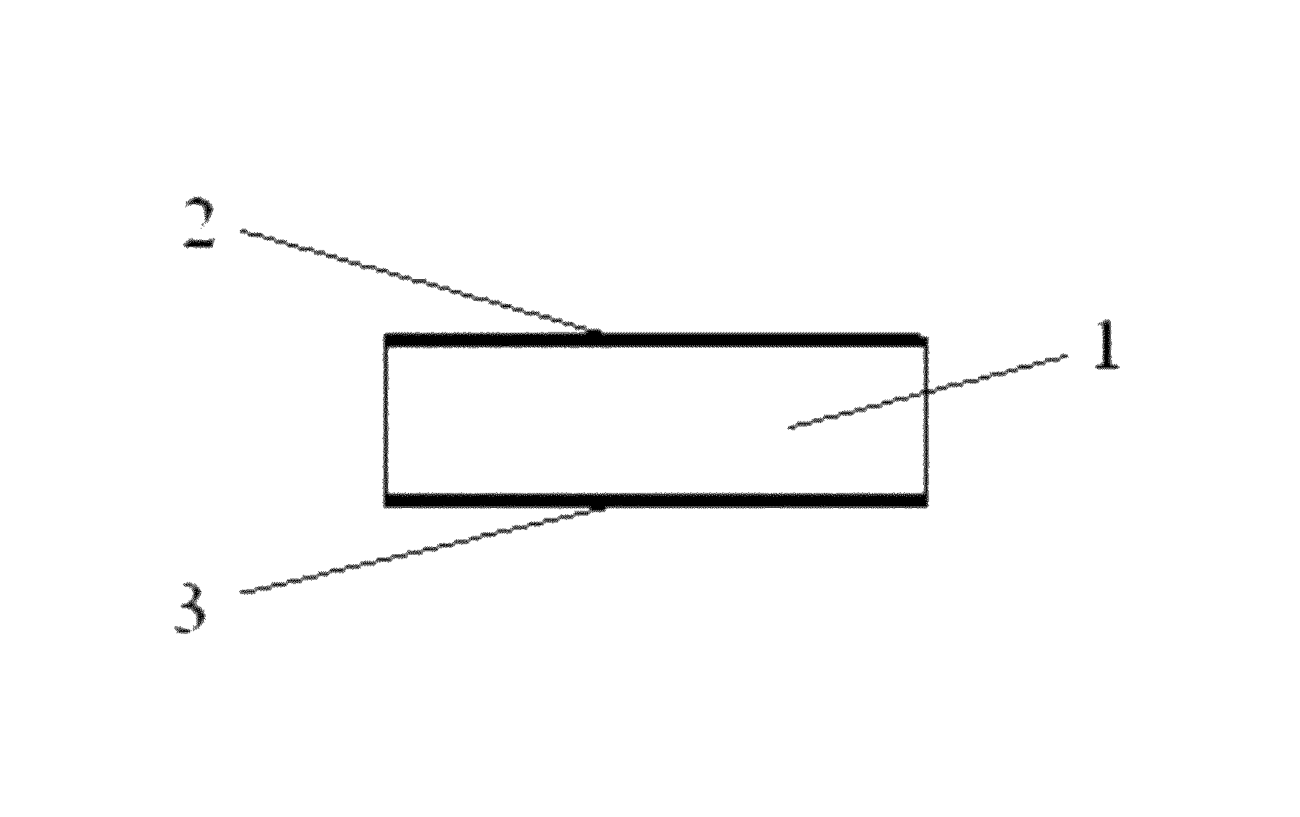
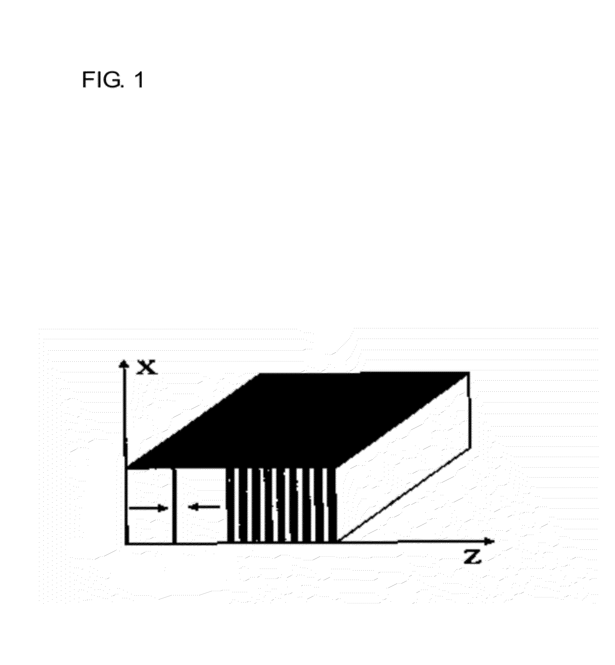
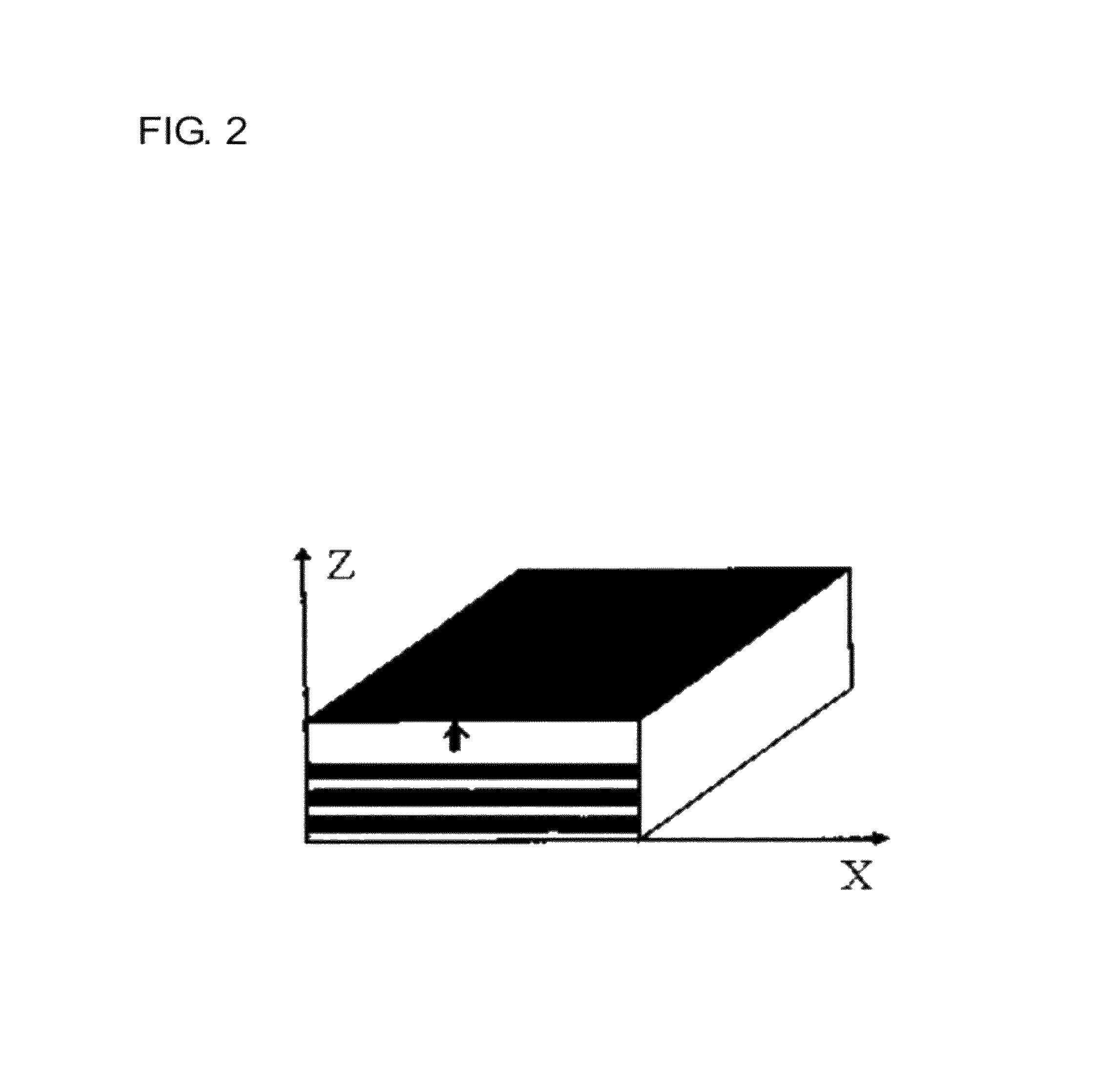
[0032]As illustrated in FIG. 3, the superlattice crystal resonator of this embodiment comprises: a substrate 1 of a dielectric acoustic superlattice crystal material, wherein a metal electrode 2 and a metal electrode 3 are respectively plated on each side of the substrate 1, both the electrode 2 and the electrode 3 being continuous single electrode. The electrode 2 is used as an electrical input, and the electrode 3 is used as an electrical output. This structure is referred to as a one-port superlattice crystal resonator. Two vibration modes may be used: a vibration mode in which the sound propagation direction is perpendicular to the electric field direction as illustrated in FIG. 1 and a vibration mode in which the sound propagation direction is parallel to the electric field direction as illustrated in FIG. 2.

[0033]A superlattice crystal material with a vibration period of 7.8 μm was selected and cut into the substrate 1 with a size of 3.7 ...

embodiment 2

Two-Port Superlattice Crystal Resonator

[0036]As illustrated in FIG. 6, the superlattice crystal resonator of this embodiment comprises: a substrate 1 of a dielectric acoustic superlattice crystal material, wherein one side of the substrate 1 was plated with a metal electrode 2 and a metal electrode 2′, of a divided rectangle shape, and the other side of the substrate 1 was plated with a undivided, continuous single electrode 3. The electrode 2 was used as an electrical input, the electrode 2′ was used as an electrical output, and the electrode 3 is connected with common ground. This structure is referred to as two-port superlattice crystal resonator, which uses a vibration mode in which the sound propagation direction is perpendicular to the electrical field direction as illustrated in FIG. 1.

[0037]A superlattice crystal material with a vibration period of 7 μm was selected and cut into the substrate 1 with a size of 8 mm×1 mm×0.5 mm, and then the substrate 1 was plated with electro...

embodiment 3

Monolithic Superlattice Crystal Filter

[0039]The superlattice crystal filter of this embodiment was formed by a two-port superlattice crystal resonator as described in Embodiment 2 (see FIG. 6). In other words, a two-port superlattice crystal resonator as described in Embodiment 2 (see FIG. 6) can perform the function of a superlattice crystal filter. This structure is referred to as monolithic superlattice crystal filter

[0040]A superlattice crystal material with a vibration period of 7 μm was selected and is cut into a substrate with a size of 8 mm×3 mm×0.5 mm, and then the substrate was plated with electrodes in the mode of FIG. 1. The dimension of electrode 3 was 8 mm×0.5 mm; electrode 2 and electrode 2′ each were a rectangle of 2 mm×0.5 mm, having a separation of 1 mm between them and a distance of 1.5 mm from each end to the border of the substrate (see FIG. 9). A monolithic superlattice crystal filter having a center frequency of 741.4 MHz, bandwidth of 600 kHz, pass-band loss ...


PUM


Abstract

A superlattice crystal resonator having a substrate of a dielectric acoustic superlattice material, both sides of which substrate are plated with electrodes. The resonator can be a one-port resonator if the electrode on both sides is a single electrode, or it can be a two-port resonator if the electrode on one side is a single electrode and the electrode on the other side is a bipolar electrode. The superlattice crystal resonator can be used as a superlattice crystal filter, either in the form of a monolithic superlattice crystal filter formed by a two-port superlattice crystal filter, or in the form of a combined superlattice crystal filter where a number of one-port superlattice crystal resonators are interconnected in various circuitry configurations with or without other electronic components, such as capacitors, inductors, and resisters.

Description

FIELD OF THE INVENTION[0001]The present invention relates to a resonator and a filter in a communication device, and more specifically, to a resonator of a dielectric, acoustic, superlattice crystal material and a filter of the same material.BACKGROUND OF THE INVENTION[0002]In recent years, the communication field has achieved notable technical progress in reducing the size and weight of a communication device such as a portable telephone. To achieve such technical progress, simplified and miniaturized components with various functions have been developed. At present, it is critical to improve the performance of the resonator and the filter used in communication devices.[0003]The existing SAW (Surface Acoustic Wave) resonator has drawbacks because it has a low power handling capacity and is difficult to process when used for a high frequency situation.[0004]The existing SAW resonator is characterized by good bandwidth selectivity (or “squareness index”), low insertion loss and small...

Claims


Application Information

Patent Timeline
Patent Type & Authority Patents(United States)
IPC IPC(8): H03H9/00H01L41/083H03H9/02H03H9/17H03H9/54H03H9/56H03H9/60
CPCH03H9/605H03H9/0095H03H9/02015H03H9/17H03H9/542H03H9/56
Inventor LIU, PINGZHU, YONGYUANWANG, JINGYU
Owner SHOULDER ELECTRONICS CO LTD
Why Eureka
Try Eureka