Coupler for coupling gyrotron whispering gallery mode RF into HE11 waveguide

a gyrotron and whispering technology, applied in the direction of transit-tube coupling devices, tubes with helical electron streams, electric discharge tubes, etc., can solve the problems of rf loss, internal mirrors must be adjustable for optimal, and modes cannot be efficiently transported as rf (radio frequency), so as to achieve efficient coupling and enhance generation

Active Publication Date: 2015-02-24
CALABAZAS CREEK RES
View PDF8 Cites 97 Cited by
  • Summary
  • Abstract
  • Description
  • Claims
  • Application Information

AI Technical Summary

Benefits of technology

[0006]A first object of this invention is a launcher for a gyrotron having an integrated mode converting first reflector coupled to a quasi-optical launcher comprising a cylindrical waveguide supporting Whispering Gallery (WG mode or WGM) and having a step cut launcher with a launch edge, the first reflector generating RF with an elliptical radiation pattern and coupling the RF into a second mode converting reflector generating free space wave for coupling into a corrugated waveguide where it propagates in an HE11 mode.
[0007]A second object of this invention is a gyrotron having a Whispering Gallery (WG) mode waveguide with a step-cut launcher, the step-cut launcher having a launch edge and coupling into a mode converting first reflector on the order of a wavelength from the step-cut launcher and launch edge, the first reflector generating RF with an elliptical radiation pattern and coupling this RF into a second mode converting reflector generating an HE11 wave for coupling into a waveguide.
[0008]The present invention is a launch coupler for a gyrotron having helically propagating energy contained by a cylindrical waveguide which terminates into a step-cut launcher having a launch edge, the RF energy propagating helically in a whispering gallery (WG) mode down the axis of a cylindrical waveguide. RF energy from the launch edge is coupled to a first mode converting reflector which is in close proximity to the launch edge, and thereafter to a second mode converting reflector which directs the propagating RF onto a path which may be parallel to the central axis, where the first mode converting reflector and second mode converting reflector have

Problems solved by technology

These modes cannot be efficiently transported as RF (radio frequency) power in a low loss transmission system.
One drawback of this approach is the internal mirrors must be adjustable for optimum performance to prevent device overheating from internal losses at the high power levels.
Additionally, since these large mirrors are external to the gyrotron cavity, the RF

Method used


Image

  • Coupler for coupling gyrotron whispering gallery mode RF into HE11 waveguide
  • Coupler for coupling gyrotron whispering gallery mode RF into HE11 waveguide
  • Coupler for coupling gyrotron whispering gallery mode RF into HE11 waveguide

Examples


Embodiment Construction

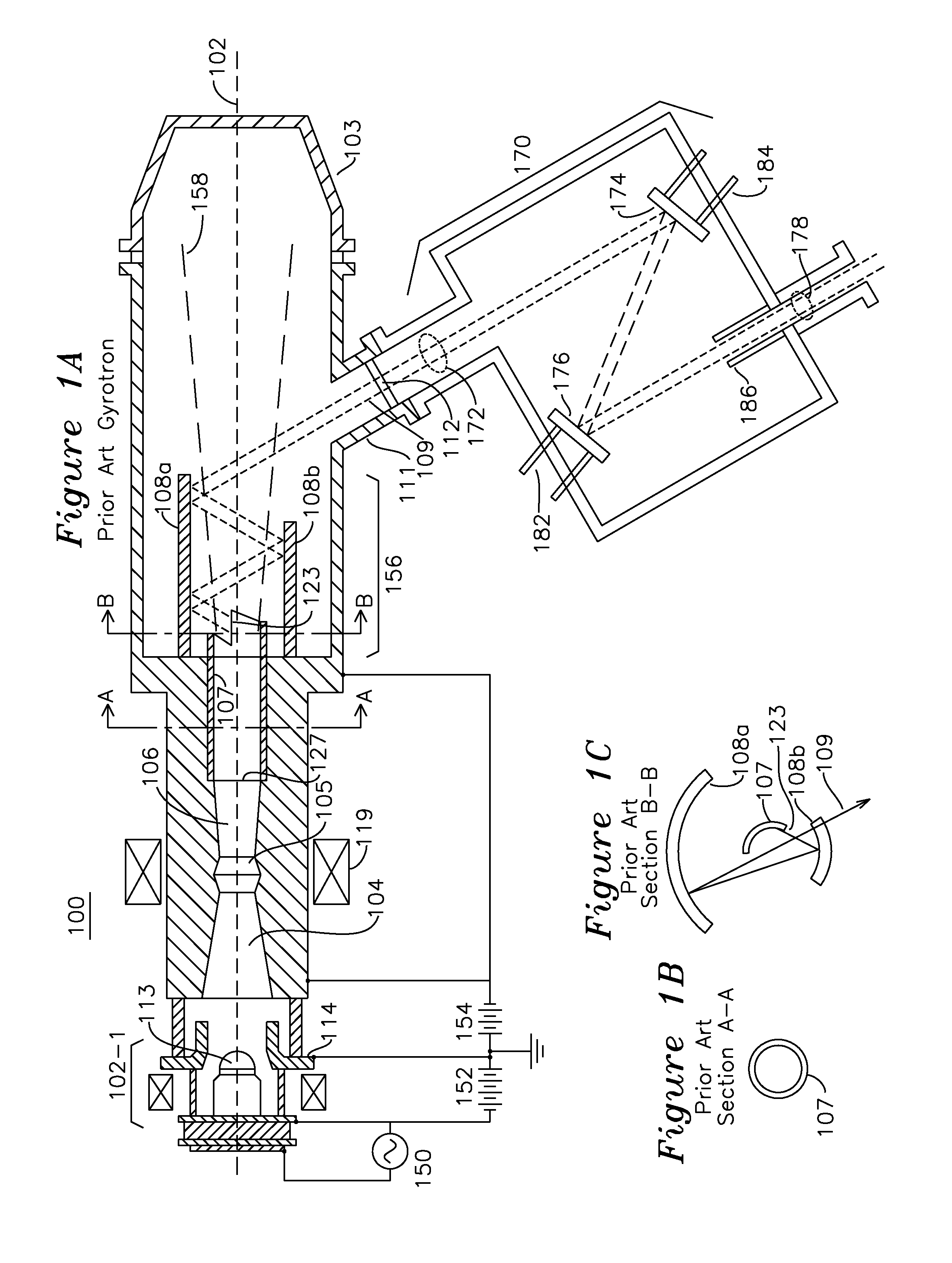
[0023]The various figures and views of the invention identify each structure with a reference numeral which is understood to indicate the same structure in other figures or views. Additionally, certain figures include orthogonal x, y, and z axis indicators to clarify the plane of the particular view. FIG. 1A shows a prior art Gyrotron 100. An electron gun assembly 102-1 produces an annular electron beam that propagates about axis 102 through input beam tunnel 104 into a cylindrical cavity 105 where electron beam energy is converted to an RF mode with the RF energy propagating helically along the waveguide. High power gyrotrons use transverse electric modes with high radial and azimuthal mode numbers. A typical mode example is TE24,6, with this high order mode RF propagating helically along the inner surface of the waveguide in a surface wave mode referred to as a whispering gallery (WG) mode. The RF propagates from the cavity 105 into a waveguide of increasing diameter 106 and into ...


PUM


Abstract

A cylindrical waveguide with a mode converter transforms a whispering gallery mode from a gyrotron cylindrical waveguide with a helical cut launch edge to a quasi-Gaussian beam suitable for conveyance through a corrugated waveguide. This quasi-Gaussian beam is radiated away from the waveguide using a spiral cut launch edge, which is in close proximity to a first mode converting reflector. The first mode converting reflector is coupled to a second mode converting reflector which provides an output free-space HE11 mode wave suitable for direct coupling into a corrugated waveguide. The radiated beam produced at the output of the second mode converting reflector is substantially circular.

Description

[0001]The present invention was developed with the U.S. Department of Energy under grant DE-FG02-05ER84181. The government has certain rights in this invention.FIELD OF THE INVENTION[0002]The present invention relates to an RF mode converter and coupler for a gyrotron. In particular, the present invention relates to an apparatus and method for coupling the RF power generated in a gyrotron cavity and traveling as whispering gallery (WG) mode in a cylindrical waveguide to the HE11 mode. In one example, WG mode is coupled from a circular waveguide to a first and second reflector for direct coupling to a corrugated waveguide.BACKGROUND OF THE INVENTION[0003]Modern high power gyrotrons produce power in high-order TE modes (TEmn modes with m,n>>1). These modes cannot be efficiently transported as RF (radio frequency) power in a low loss transmission system. In addition, it is advantageous to separate the RF transmission from that of the spent electron beam within the gyrotron. Both ...

Claims


Application Information

Patent Timeline
IPC IPC(8): H01J23/40
CPCH01J23/40H01J25/025
Inventor NEILSON, JEFFREY M.
Owner CALABAZAS CREEK RES
Why Eureka
Try Eureka