Method and device for shielding a high-power laser apparatus and high-power-laser optical system employing such a device

a laser apparatus and shielding technology, applied in the field of high-power lasers, can solve the problems that the shielding method is not always satisfactory for all operating conditions of high-power laser apparatuses, and achieve the effects of reducing damage risks, avoiding deterioration of high-power apparatuses, and improving control

Inactive Publication Date: 2015-03-03
IMAGINE OPTIC +1
View PDF12 Cites 19 Cited by
  • Summary
  • Abstract
  • Description
  • Claims
  • Application Information

AI Technical Summary

Benefits of technology

[0016]The aim of the present invention is to propose a method of shielding that makes it possible to limit the risks of damage in a high-power laser apparatus, and which is more effective than the methods used at present.
[0019]Thus, providing phase correction upstream of the spatial filter pinhole offers better control of the function of spatial filtering and makes it possible to avoid deterioration of the high-power apparatuses.
[0020]In fact, to perform the role of shielding the optical elements of a high-power laser more effectively and reduce the risks of damage connected with the two main causes described above, the present invention proposes the concept of an optical fuse by combining a filter pinhole that is small enough to perform a very effective filtering function (typically less than a few times the diffraction limit, typically less than 10) with a phase correction system positioned upstream of the filter pinhole, the main function of which is to permit, in nominal operation, focusing of the laser beam that is sufficiently close to the ideal spot (close to the limit set by diffraction) so that almost all of the energy passes through the filter pinhole.
[0022]on the one hand, to remove, from the wave front of the laser beam, all of the residual aberrations at spatial frequencies that can give rise, by propagation, to hot spots on the laser beam. These residual aberrations are aberrations which are: either generated by the laser upstream of the correction system and cannot be corrected by the correction system (insufficient degree of freedom in the correcting element, for example), or generated by the correcting element itself (for example, printing effect of a deformable mirror of the bimorphic type). Thus, the beam coming from the filter pinhole no longer presents risks of damage by propagation of the optical elements located directly downstream;
[0023]on the other hand, to block the bulk of any luminous flux returning from the target, which can itself be amplified by the amplifiers located between the target and the filter pinhole. The smaller the diameter of the filter pinhole, the better the blocking of the flux returning from the target is. In this configuration, the filter pinhole provides shielding of the optical elements upstream (located between the generation of the laser beam and the filter pinhole).
[0036]The spatial filtering of the laser beam is provided by a filter pinhole the size of which is advantageously selected so as to eliminate, from the beam, the aberrations at spatial frequencies that can give rise, by propagation, to serious surges in this beam.

Problems solved by technology

However, the existing methods of shielding are not always satisfactory for all operating conditions of high-power laser apparatuses.

Method used


Image

  • Method and device for shielding a high-power laser apparatus and high-power-laser optical system employing such a device
  • Method and device for shielding a high-power laser apparatus and high-power-laser optical system employing such a device
  • Method and device for shielding a high-power laser apparatus and high-power-laser optical system employing such a device

Examples


Embodiment Construction

[0057]Referring to the aforementioned figures, two options for implementing a shielding device according to the invention, employed in a high-power-laser optical system, will now be described.

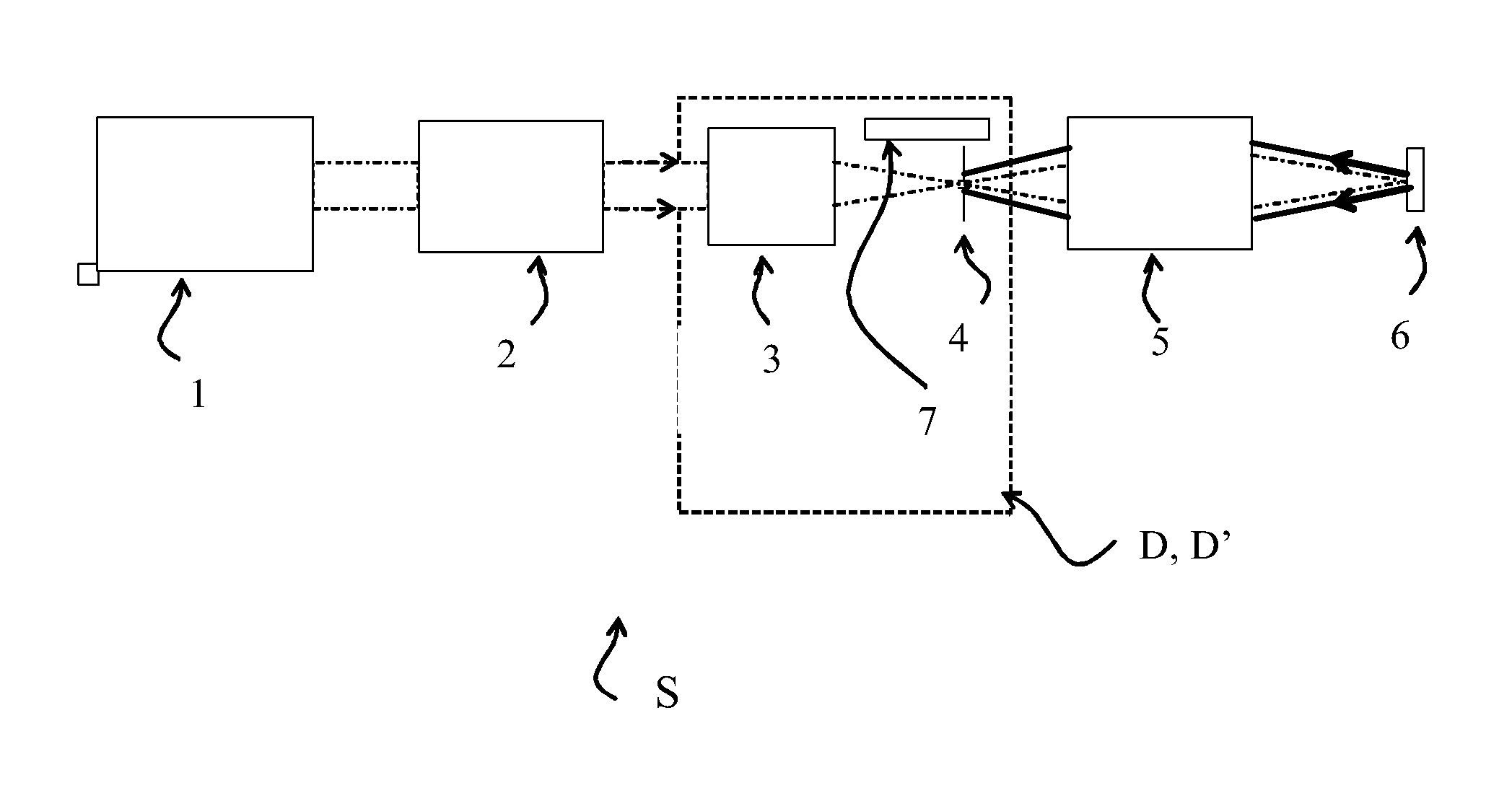
[0058]Such an optical system S comprises, referring to FIG. 1, a module 1 for generating a laser beam, a module 2 for amplifying the beam, a shielding device D,D′ according to the invention, and a module 5 for amplification and / or for compression and for focusing towards a target 6.

[0059]It should be noted that for greater clarity, the mirrors, lenses and other afocals for beam shaping and transport are not shown in FIG. 1.

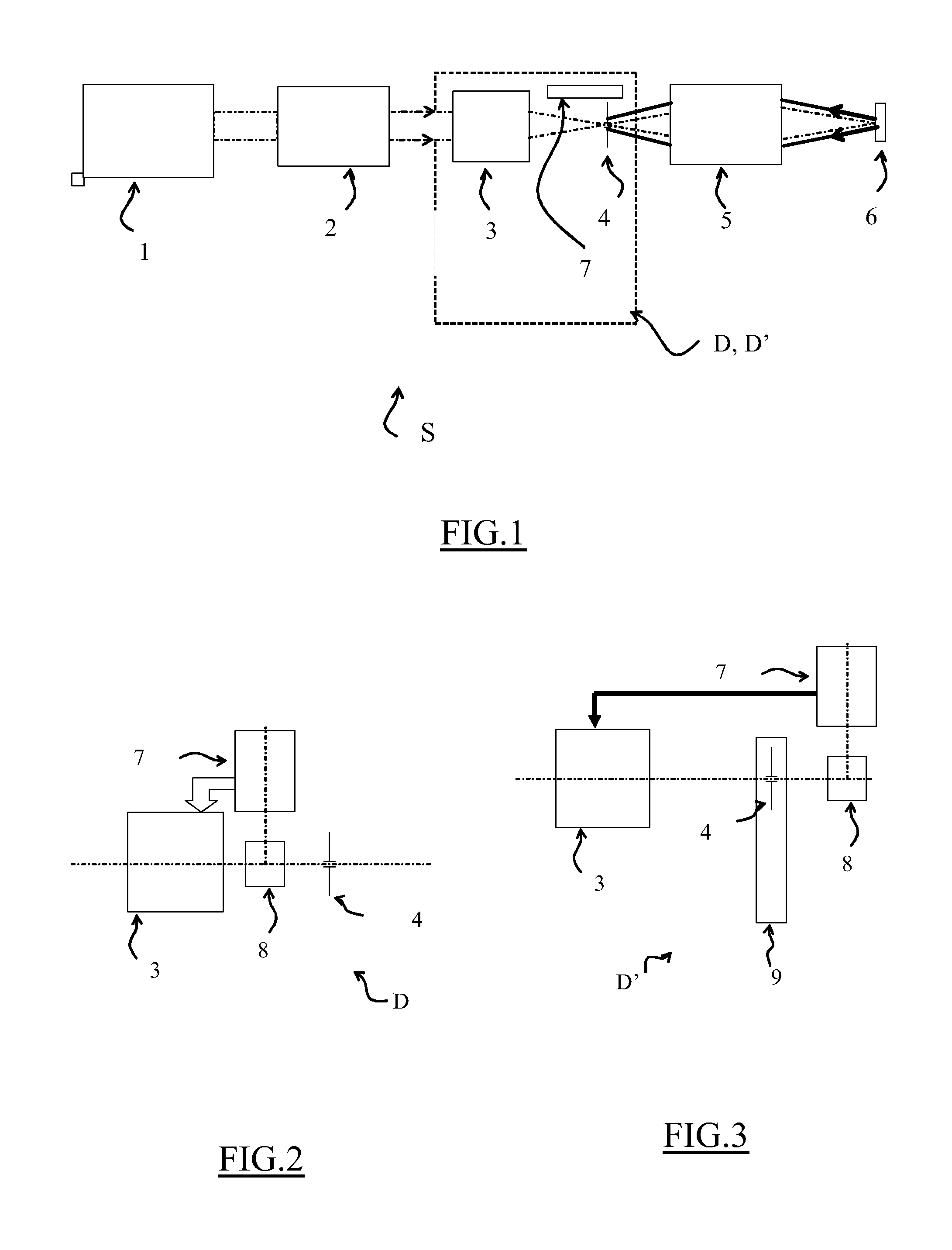
[0060]The shielding device D,D′ according to the invention comprises a phase correction module 3 arranged downstream of the amplification module 2, a spatial filter pinhole 4 arranged between the exit of this correction module 3 and the entrance of the amplification module 5, and an aberration measuring module 7.

[0061]In a first option for carrying out the invention, the shie...


PUM


Abstract

Method for shielding a high-power laser apparatus (S) in which a laser beam is generated and then amplified in at least a first amplification stage, including spatial filtering (4) of the amplified laser beam, phase correction (3) carried out on the laser beam before it is spatially filtered, and a measurement of the aberrations (7) on the laser beam. The phase of the beam is corrected so as to produce a beam having minimal aberrations after spatial filtering. The shielding device (D, D′) implementing this method may in particular be employed in apparatus using an intense laser beam of high (terawatt) peak power and in proton therapy units.

Description

BACKGROUND OF THE INVENTION[0001]1. Field of the Invention[0002]The present invention relates to a method for shielding a high-power laser apparatus. It also relates to a shielding device using this method, as well as a high-power-laser optical system employing such a device.[0003]The field of the invention is that of high-power lasers, and more particularly of ultra-intense lasers.[0004]2. Description of the Related Art[0005]Apparatuses based on ultra-intense lasers are subject to risks of damage. These risks are of two types:[0006]During amplification of the pulse: when the distribution of pulse energy incident on an amplifier is non-uniform, and contains “hot spots”, interaction with the crystal creates a very high risk of damage. Such damage leads to the stopping of the laser and the need to replace the damaged optics: this therefore causes delays, as well as costs that can amount to several tens of thousands of Euros when the damaged elements are the amplifier crystals or the c...

Claims


Application Information

Patent Timeline
Patent Type & Authority Patents(United States)
IPC IPC(8): H01S3/13G02B26/06G02B27/46H01S3/00H01S3/23
CPCH01S3/0078G02B26/06G02B27/46H01S3/0014H01S3/2316H01S3/005
Inventor LEVECQ, XAVIERRIBOULET, GILLES
Owner IMAGINE OPTIC
Why Eureka
Try Eureka