
Therapeutic light delivery apparatus, method, and system

a technology of light delivery apparatus and light source, which is applied in the field of therapeutic light delivery apparatus, method and system, can solve the problems of affecting the performance of conventional phototherapy devices incorporating a metallic housing, and affecting the operation of the devi

Inactive Publication Date: 2015-03-17
NOMIR MEDICAL TECH
View PDF15 Cites 2 Cited by
  • Summary
  • Abstract
  • Description
  • Claims
  • Application Information

AI Technical Summary

Benefits of technology

[0019]A significant advantage the present invention over prior art devices is that coupling and positioning between multiple source fibers, the integrating optical fiber, the housing, the buffer, and the optical element enables a substantially improved precise and stable uniform beam in a durable construction unaffected by the extreme thermal cycling of sterilization and other treatments. Another advantage is that the assembly of the device is performed at room temperature, so the heat sensitive optical components and claddings are not negatively affected. According to a preferred embodiment of the invention, the housing is made from a material having a coefficient of thermal expansion approximately equal to the coefficient of thermal expansion of the buffer. In this manner, both the housing and the buffer will thermally expand (and contract) approximately the same amount, thus minimizing the effects of heat cycling on the device.
[0079]In some embodiments, directing the therapeutic light to be transmitted to the treatment site to illuminate at least a portion of the treatment site with a prescribed illumination pattern includes providing substantially uniform illumination of at least a portion of the illuminated portion of the treatment site.

Problems solved by technology

The universal rise of bacteria, fungi and other biological contaminants resistant to antimicrobial agents presents humanity with a grievous threat to its very existence.
The performance of such conventional phototherapy devices incorporating a metallic housing has proven less than optimal.
Additional problems associated with such conventional phototherapy devices include loosening of the optical element due to thermal cycling, as the metallic housing and the optical element, as well as the optical fiber, have significantly different thermal characteristics, such as the coefficient thermal expansion.
Thus, during the application of radiation, the housing tends to expand greater than both the optical fiber and the optical element, resulting in loosening of the connection between the housing, the optical fiber and optical element, often breaking adhesive bonds.
The use of epoxies to hold the elements can be troublesome, since the epoxies have limited operating temperatures, may absorb part of the radiation, and darken as they degrade.
When an epoxy darkens it absorbs more radiation which can then lead to a thermal runaway failure.
This technique although effective, requires a complex thermoforming machine, and can damage the system's optical elements by exposing them to the 500 degrees C. it takes to melt the fluoro-polymers together.
This technique can also not be used when the fiber and cuff are not similar materials.
Biophotonic responses are complex and unpredictable variations in illumination may result in unnecessary damage to healthy tissues by overheating, or the survival of malignant pockets by under treating, among other side effects.

Method used


Image

  • Therapeutic light delivery apparatus, method, and system
  • Therapeutic light delivery apparatus, method, and system
  • Therapeutic light delivery apparatus, method, and system

Examples


examples

[0311]The following examples are included to demonstrate exemplary embodiments of the present invention and are not intended to limit the scope of the invention. Those of skill in the art, will appreciate that many changes can be made in the specific embodiments and still obtain a like or similar result without departing from the spirit and scope of the present invention.

example i

[0312]

TABLE 2MIC values for Susceptible, Intermediate and Resistant S. aureusMinimum Inhibitory Concentration (MIC) InterpretiveStandards (μg / ml) for Staphylococcus sp.Antimicrobial AgentSusceptibleIntermediateResistantPenicillin≦0.12—≧0.25Methicillin≦8—≧16AminoglycosidesGentamicin≦48≧16Kanamycin≦1632 ≧64MacrolidesErythromycin≦0.51-4≧8TetracyclineTetracycline≦48≧16FluoroquinoloneCiprofloxacin≦12≧4Folate Pathway InhibitorsTrimethoprim≦8—≧16AnsamycinsRifampin≦12≧4

example ii

Bacterial Methods: NIMELS Treatment Parameters for In Vitro MRSA Experiments

[0313]The following illustrates the general antibacterial methods according to the invention, using a MRSA model for the in vitro Experiments V and VIII-XII.

A. Experiment Materials and Methods for MRSA:

[0314]

TABLE 3Method: for CFU countsTimeFTE(hrs)Task(hrs)T −18Inoculate overnight culture150 ml directly from glycerol stockT −4Set up starter cultures1Three dilutions 1:50, 1:125, 1:250 LB MediaMonitor OD600 of starter cultures4T 0Preparation of plating culture1At 10:00 am, the culture which is at OD600 = 1.0 isdiluted 1:300 in PBS (50 mls final volume) and stored atRT for 1 hour.(Room temp should be ~25° C.)T +1Seeding of 24-well plates12 ml aliquots are dispensed into pre-designated wells in24-well plates.T +2Dilution of treated samples4to +8After laser treatment, 100 μl from each well is dilutedserially to a final dilution of 1:1000 in PBS.Plating of treated samples2100 μl of final dilution is plated in qui...


PUM


Abstract

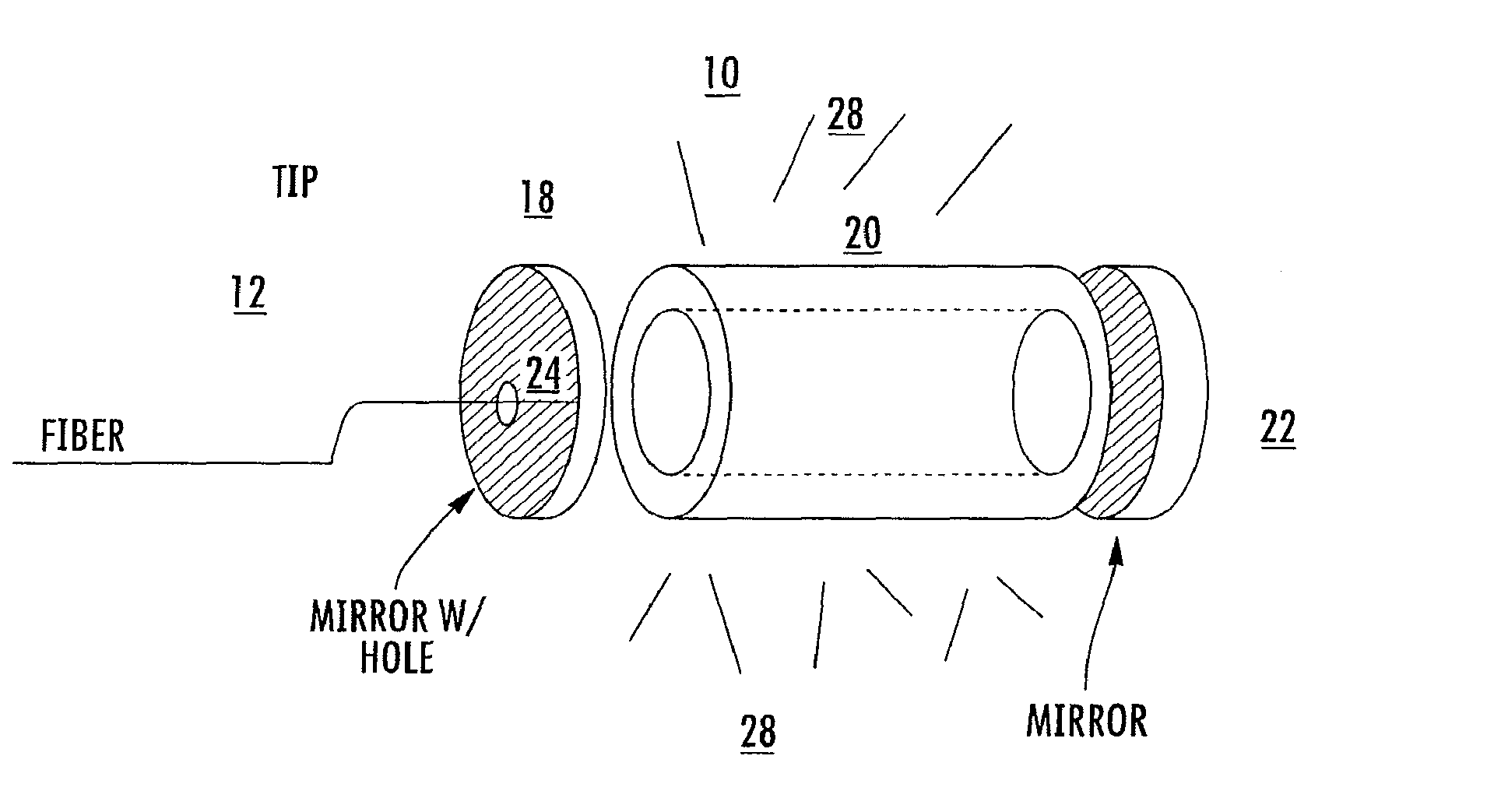
An optical delivery apparatus is disclosed including: an optical fiber extending between a distal end having a distal end face and a proximal end having a proximal end face, an optical element positioned to receive the light emitted from the distal end face and direct the light to an illumination region; and a non-metallic housing containing the optical fiber and the optical element and maintaining the relative position of the optical fiber and the optical element.

Description

RELATED APPLICATIONS[0001]This application is a continuation of U.S. patent application Ser. No. 13 / 246,447, filed Sep. 27, 2011, which is a continuation of U.S. patent application Ser. No. 13 / 058,765, filing date not yet assigned, which is the U.S. National Stage of PCT International Application No. PCT / US2009 / 053752, filed Aug. 13, 2009, which claims the benefit under 35 USC 119(e) of U.S. Provisional Patent Application No. 61 / 088,401, filed Aug. 13, 2008.[0002]U.S. patent application Ser. No. 13 / 058,765 is additionally a continuation-in-part of U.S. patent application Ser. No. 11 / 981,486, filed Oct. 31, 2007, which claims the benefit under 35 USC 119(e) of U.S. Provisional Patent Application No. 60 / 874,424, filed Dec. 12, 2006.[0003]U.S. patent application Ser. No. 11 / 981,486 is a continuation-in-part of U.S. patent application Ser. No. 10 / 776,106, filed Feb. 11, 2004 and of PCT International Patent Application No. PCT / US2006 / 028616, filed Jul. 21, 2006, which claims the benefit ...

Claims


Application Information

Patent Timeline
Patent Type & Authority Patents(United States)
IPC IPC(8): G02B6/00A61B18/22A61B1/07A61N5/06A61N5/067
CPCA61N5/062A61N2005/063A61N2005/067A61N2005/0659A61N5/067
Inventor BORNSTEIN, ERICSINOFSKY, EDWARD
Owner NOMIR MEDICAL TECH
Learn More