
Thermal energy storage and recovery device and system having a heat exchanger arrangement using a compressed gas

a heat exchanger and recovery device technology, applied in the direction of indirect heat exchangers, machines/engines, light and heating apparatus, etc., can solve the problems of complex mechanical arrangement of system components and known system to be not flexible, and achieve the effect of increasing efficiency, efficient heat generation, and high efficiency of heat generating arrangements

Active Publication Date: 2015-03-31
SIEMENS GAMESA RENEWABLE ENERGY AS
View PDF25 Cites 35 Cited by
  • Summary
  • Abstract
  • Description
  • Claims
  • Application Information

AI Technical Summary

Benefits of technology

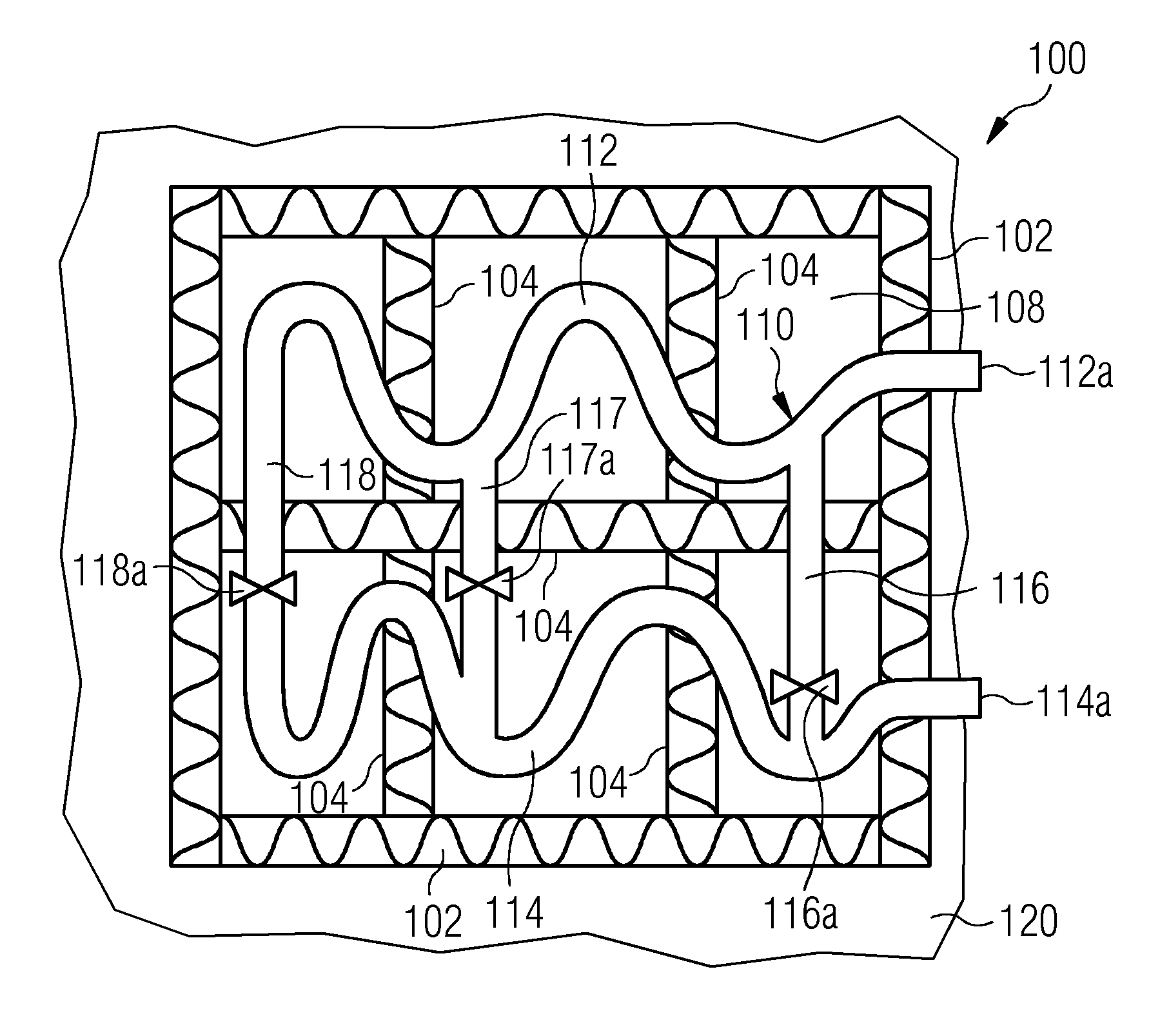
[0010]The described thermal energy storage and recovery device is based on the idea that by employing a heated up compressed gas as an input (e.g. via the first end) to the thermal energy storage and recovery device a very high efficiency of the thermal energy storage is possible. Thereby, energy and in particular mechanical energy being left in compressed gas which is returned from the thermal energy storage and recovery device as an output (e.g. via the second end) can be used to help driving a compression procedure resulting in the heated up compressed air being fed to the first end of the heat exchanger arrangement.
[0052]A rotating shaft of the steam turbine may be connected to an electric power generator, which is capable of converting the mechanical energy being provided by the steam turbine into electric energy, which can be easily fed to a power grid and / or which can be directly consumed by at least one electric consumer.

Problems solved by technology

One disadvantage of this wind-powered energy production and storing system is that there is a direct mechanical connection between the energy storage and recovery system and the wind turbine and that all the energy storage equipment, besides the storing stations, is placed in the wind turbine resulting in a complex mechanical arrangement of the system components.
This causes the known system to be not flexible.

Method used


Image

  • Thermal energy storage and recovery device and system having a heat exchanger arrangement using a compressed gas
  • Thermal energy storage and recovery device and system having a heat exchanger arrangement using a compressed gas
  • Thermal energy storage and recovery device and system having a heat exchanger arrangement using a compressed gas

Examples


first embodiment

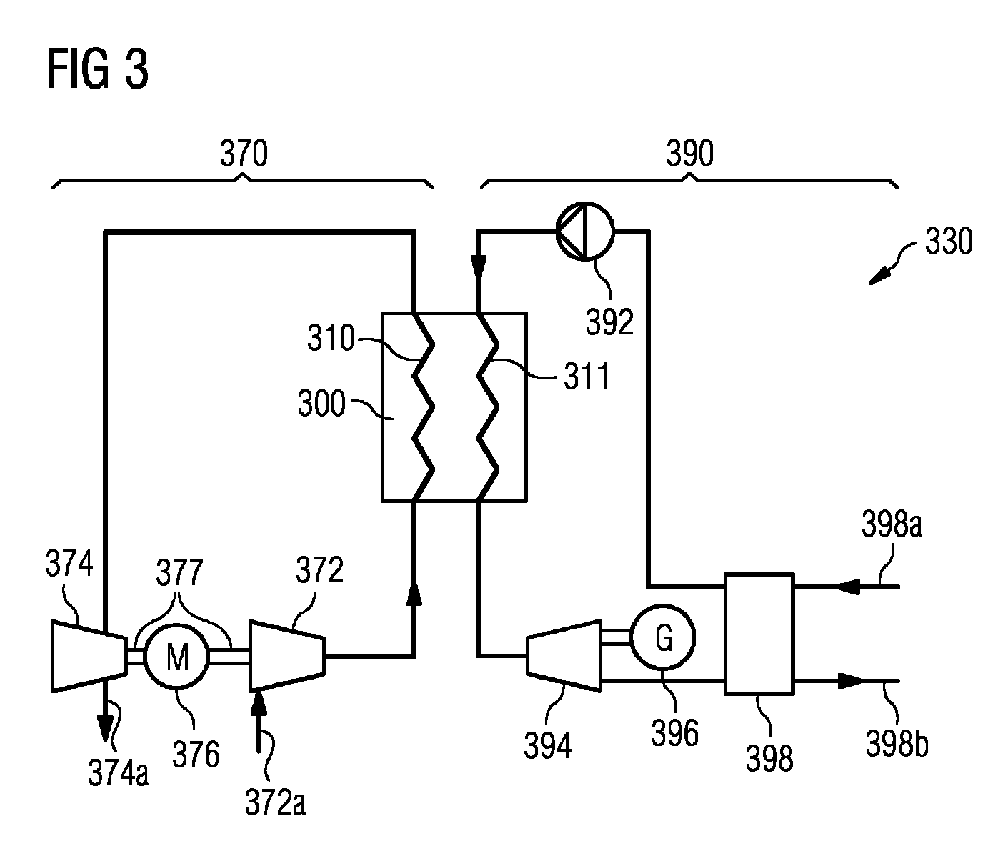
[0079]FIG. 3 shows a schematic illustration of a thermal energy storage and recovery system 330 in accordance with the invention. To store energy within a thermal energy storage and recovery device 300 a heat generating arrangement 370 is used. To recover energy from the thermal energy storage and recovery device 300 a heat consumption arrangement 390 is used.

[0080]As can be seen from FIG. 3, the heat generating arrangement 370 comprises a compressor 372, which is driven be a motor 376. The compressor 372 comprises an air inlet 372a. The air in the air inlet 372a may have a temperature of e.g. 20 Celsius degrees and a pressure of e.g. 1 bar. During compression of the air the pressure may rise to e.g. 25 bar and the temperature may rise to e.g. 500 Celsius degrees. This heated up and compressed air is fed into an inlet of a heat exchanger arrangement 310 of the thermal energy storage and recovery device 300. The compressed air then returns via an outlet of the heat exchanger arrangem...

second embodiment

[0087]FIG. 4 shows a schematic illustration of a thermal energy storage and recovery system 430 in accordance with the invention. In this embodiment, a district heating installation or a thermal power generation plant 435 is connected to a utility grid 450 and to a thermal energy storage and recovery device 400. According to the embodiment described here the district heating installation or power generation plant 435 comprises a steam turbine 440 with a condenser (not shown) and a connected electrical power generator 445 and a compressor 472 with a built in motor. The compressor 472 may be replaced by an electrical boiler or may be supplemented by means of a heat pump system or other heating means.

[0088]The district heating installation or thermal power generation plant 435 is connected to the thermal energy storage and recovery device 400 both for energy storage and for recovering of stored energy. Also here a wind turbine 460 or other kind of alternative energy resources may be co...


PUM


Abstract

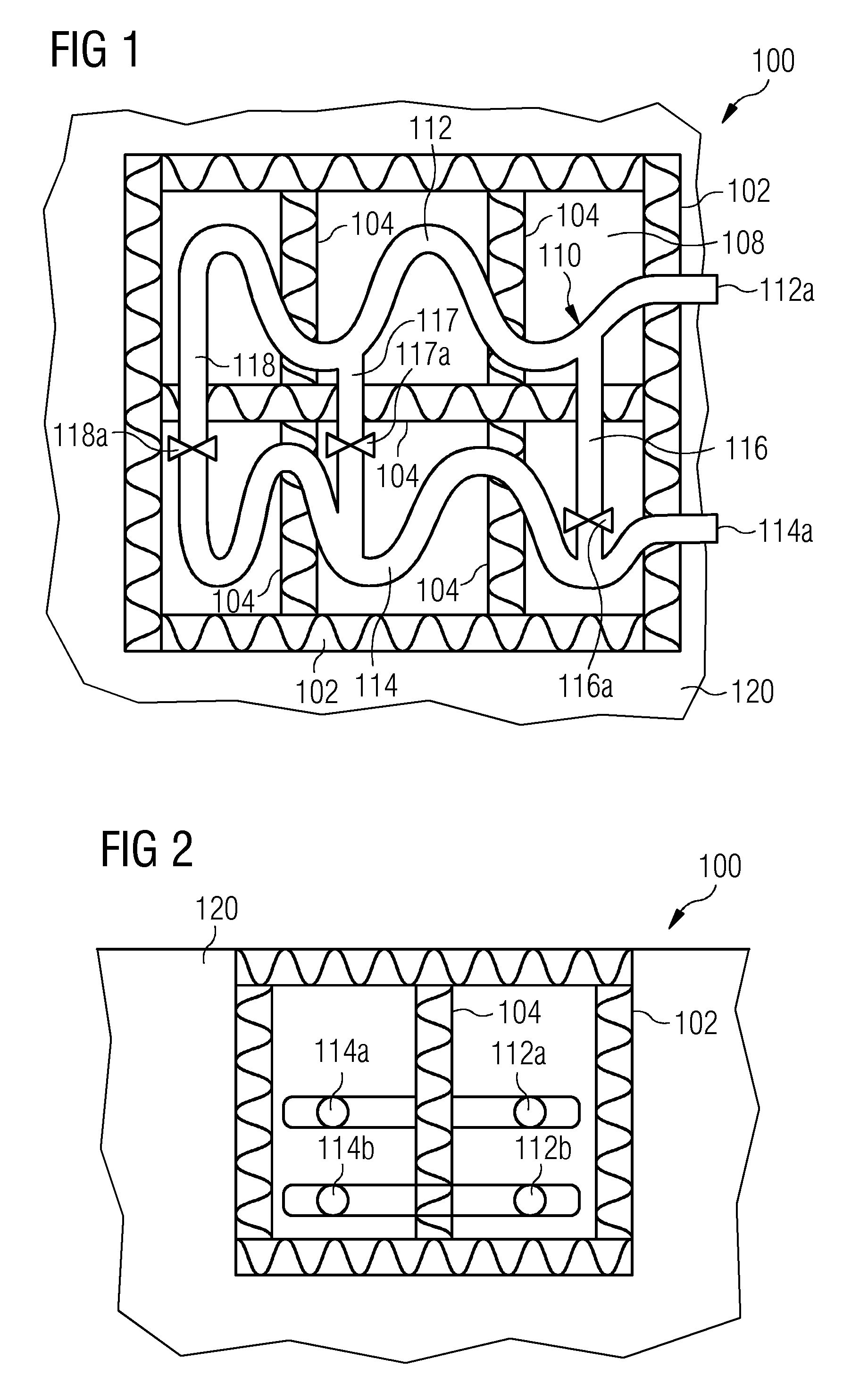
A thermal energy storage and recovery device is disclosed which includes a heat exchanger arrangement configured for guiding a flow of a heat transfer medium between a first end and a second end, and a heat storage material surrounding the heat exchanger arrangement so that a thermal interaction region is formed for thermally coupling the heat transfer medium with the heat storage material. The heat exchanger arrangement is sealed against the heat storage material so that, when in a first operational mode, in which the heat storage material is supposed to receive thermal energy from the heat transfer medium, a compressed gas is usable as the heat transfer medium for transferring thermal energy from the heat transfer medium to the heat storage material.

Description

[0001]CROSS REFERENCE TO RELATED APPLICATIONS[0002]This application is the US National Stage of International Application No. PCT / EP2011 / 056378, filed Apr. 20, 2011 and claims the benefit thereof. The International Application claims the benefits of European Application No. 10007149.7 filed Jul. 12, 2010 and European Application No. 10190006.6 filed Nov. 4, 2010. All of the applications are incorporated by reference herein in their entirety.FIELD OF INVENTION[0003]The present invention relates to the field of temporarily storing thermal energy. In particular, the present invention relates to a thermal energy storage and recovery device comprising a heat exchanger arrangement and a heat storage material. Further, the present invention relates to a thermal energy storage and recovery system comprising such a thermal energy storage and recovery device.ART BACKGROUND[0004]The production of electric power from various types of alternative energy sources such as for instance wind turbines...

Claims


Application Information

Patent Timeline
Patent Type & Authority Patents(United States)
IPC IPC(8): F02C1/05F01K25/02F01K3/00F02C6/14F28D17/04F28D20/00F28F27/02
CPCF28D17/04F02C6/14F28D20/00F28D20/0056F28F27/02F01K3/004F05D2220/72F05D2220/76Y02E20/14Y02E60/142Y02E60/14
Inventor STIESDAL, HENRIK
Owner SIEMENS GAMESA RENEWABLE ENERGY AS
Learn More