
Drive system for a motor vehicle and motor vehicle having such a drive system

a technology for driving systems and motor vehicles, which is applied in the direction of engines, machines/engines, engine starters, etc., can solve the problems of increasing friction losses, increasing fuel consumption and emissions of pollutants, and unable to decouple the internal combustion engine. , to achieve the effect of avoiding friction losses and reducing space requirements

Active Publication Date: 2015-03-31
DR ING H C F PORSCHE AG
View PDF21 Cites 6 Cited by
  • Summary
  • Abstract
  • Description
  • Claims
  • Application Information

AI Technical Summary

Benefits of technology

The invention is a drive system for vehicles that includes an internal combustion engine and at least one electric machine. The first electric machine is connected to the drive axle or the transmission, but not directly to the engine. This allows for torque to be fed into the system without causing drag or friction losses. The system also has a third electric machine that acts as a starter for the engine, ensuring reliable starting. The second electric machine is connected to the inner crankshaft of the engine through a belt drive, which results in a quiet, efficient connection. The system can be a double-clutch transmission, which allows for interruption-free torque transmission. The first electric machine can be connected to the drive axle or the output shaft through axial gearing, which reduces space requirements. The first electric machine has a clutch device to prevent simultaneous operation and friction losses. Overall, this drive system improves the vehicle's performance and efficiency.

Problems solved by technology

Frequent starting processes and acceleration processes that occur, for example, in urban traffic, preferably are carried out or assisted by the electric machine in a hybrid motor vehicle since the operation of the internal combustion engine with frequent load changes results in increased fuel consumption and emissions of pollutants.
However, the direct connection of the belt starter generator to the internal combustion engine disadvantageously makes it possible to drive the vehicle axles solely with the belt starter generator only if the internal combustion engine is entrained.
Thus, friction losses increase.
Decoupling the internal combustion engine also is impossible during the conversion of kinetic energy of the hybrid vehicle into electric energy by means of the belt starter generator.
As a result, the internal combustion engine also generates drag torques and friction losses during the conversion of braking energy.

Method used


Image

  • Drive system for a motor vehicle and motor vehicle having such a drive system
  • Drive system for a motor vehicle and motor vehicle having such a drive system
  • Drive system for a motor vehicle and motor vehicle having such a drive system

Examples


Embodiment Construction

[0024]In the figures of the drawing, the same reference symbols denote identical or functionally identical components, unless otherwise stated.

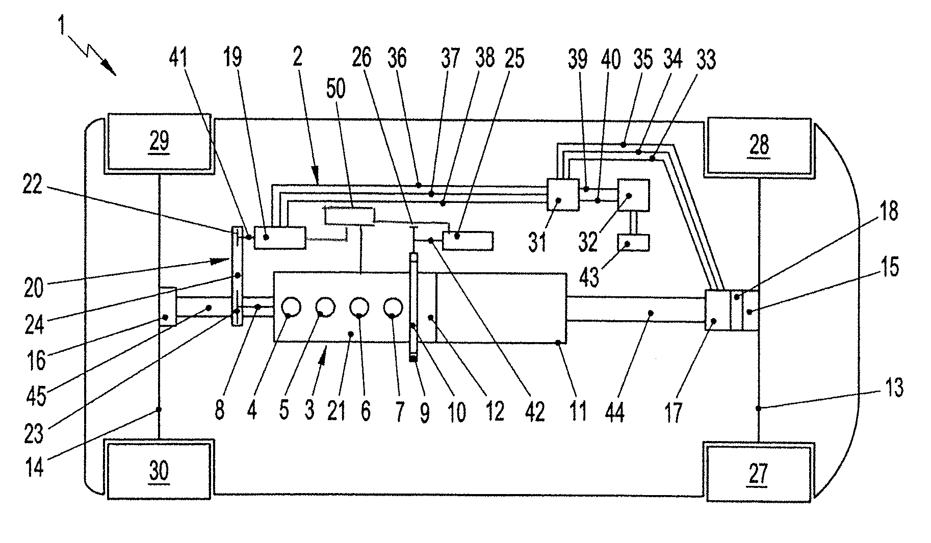
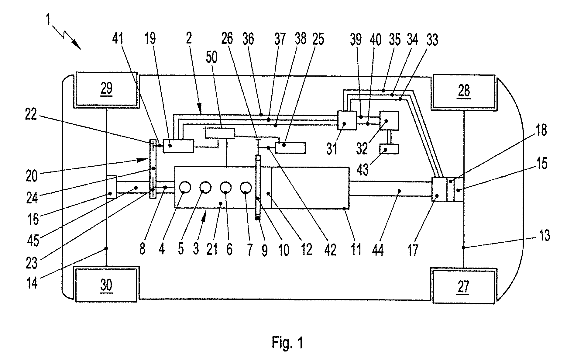
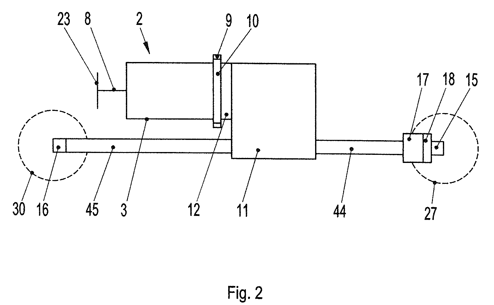
[0025]FIGS. 1 to 2 illustrate a motor vehicle 1 with a preferred embodiment of a drive system 2. The drive system 2 preferably has an internal combustion engine 3. The internal combustion engine 3 has, for example four cylinders 4-7. Four cylinders is optional and the internal combustion engine 3 can have more or fewer cylinders. The internal combustion engine 3 also has a crankshaft 8 and a starter ring gear 9, which is provided, for example, on a flywheel 10 of the internal combustion engine 3. The flywheel 10 preferably is mounted fixedly on the crankshaft 8. The internal combustion engine 3 has a housing, which is essentially in the shape of a right parallelepiped, and the crankshaft 8 passes through, for example, the entire length of the housing 21. The flywheel 10 is arranged, for example, on a narrow side of the housing 21.

[0026]The dr...


PUM


Abstract

A drive system (2) for a motor vehicle (1) has a transmission (11) for driving at least one drive axle (13, 14) of the motor vehicle (1). An internal combustion engine (3) optionally is connected operatively to the transmission (11) or decoupled therefrom. A first electric machine (17) optionally is connected operatively to the at least one drive axle (13, 14) or to an output shaft (39) of the transmission (11) or decoupled therefrom. A second electric machine (19) is connected operatively to the internal combustion engine (3).

Description

CROSS REFERENCE TO RELATED APPLICATION[0001]This application claims priority under 35 USC 119 to German Patent Application No 10 2010 036 321.9 filed on Jul. 9, 2010, the entire disclosure of which is incorporated herein by reference.BACKGROUND OF THE INVENTION[0002]1. Field of the Invention[0003]The invention relates to a drive system for a motor vehicle and to a motor vehicle having such a drive system. The invention can be applied to any motor vehicles, but the invention and the problems on which it is based are explained in more detail with respect to a passenger motor vehicle.[0004]2. Description of the Related Art[0005]A hybrid vehicle generally denotes a vehicle with a drive system that has plural drive units, for example an internal combustion engine and an electric machine. Parallel hybrid drives permit the electric machine and the internal combustion engine to apply a torque to a transmission either alternatively or cumulatively and are used to generate an energetic effici...

Claims


Application Information

Patent Timeline
Patent Type & Authority Patents(United States)
IPC IPC(8): F16H37/06B60K6/20B60W20/00B60K6/442B60K6/448B60K6/48B60K6/52B60W10/06B60W10/08B60W10/113
CPCB60K6/448B60K6/48B60K6/52B60W10/06B60W10/08B60W10/113B60W20/00B60K6/442B60K2006/4808B60K2006/4825B60K2006/4833Y02T10/6221Y02T10/6243Y02T10/6252Y02T10/626Y02T10/6265Y02T10/6286Y02T10/6234F02N11/006F02N11/04Y10T74/19Y10T74/19014Y10T74/19051Y02T10/62B60K2006/268F02N11/00B60K6/22
Inventor FUECHTNER, MARTIN
Owner DR ING H C F PORSCHE AG
Learn More