Energy filter for charged particle beam apparatus

a technology of energy filter and beam, which is applied in the direction of beam deviation/focusing by electric/magnetic means, instruments, mass spectrometers, etc., can solve the problems of inability to apply a pure energy-dependent filtering method, limitation on the acceptable emission angle spread and the acceptable size of the fov, etc., to achieve high uniformity of energy-discrimination powers, high contrast, and high resolution

Active Publication Date: 2015-04-07
ASML NETHERLANDS BV
View PDF8 Cites 12 Cited by
  • Summary
  • Abstract
  • Description
  • Claims
  • Application Information

AI Technical Summary

Benefits of technology

[0015]The object of this invention is to provide an energy filter of reflection type to realize energy-discrimination detection in a charged particle apparatus. By specifically providing a means inside the energy filter to directly adjust the incident situation of a charged particle beam onto a potential barrier of the energy filter, the energy filter can provide a fine energy-discrimination power at a center of a FOV and a high uniformity of energy-discrimination powers over the entire FOV. Furthermore, by specifically arranging detectors associated with the energy filter to separately detect SEs and BSEs within different energy ranges, images respectively comprising topography contrast and / or voltage contrast, and material contrast can be obtained simultaneously. Hence, this invention provides an effective way to realize energy-discrimination detection which can provide multiple images with high contrast and high resolution in a LVSEM and the related apparatuses based on LVSEM principle, such as the defect inspection and defect review in semiconductor yield management.
[0016]Accordingly, the invention provides a means to improve the filtering function of an energy filter of reflection type. The means uses a beam-adjusting lens on the entrance side of the potential barrier of the energy filter to make an incident charged particle beam become a substantially parallel beam to be incident onto the potential barrier.
[0027]The invention also provides a method for improving performance of an energy filter of reflection type for a charged particle beam, which comprises a step of providing a beam-adjusting lens on an entrance side of a potential barrier of the energy filter, wherein the beam-adjusting lens is excited to make the charged particle beam become a substantially parallel beam to be incident onto the potential barrier.

Problems solved by technology

Although the resolution of an image in the LVSEM is fundamentally determined by the aberrations of the electron optics thereof, however many factors can deteriorate it.
The large spread in emission angles makes it difficult to realize a pure energy-depending filtering, and the real filtering function depends on electron emission angle more or less.
This method can not be used to an application requiring a strong extraction field on the specimen surface to make more electrons escape from specimen surface or get high resolution.
Furthermore, although the hollow electrode incurs no electron loss due to lack of the electrons hitting on the wires of the grid electrode, the dramatically deteriorated energy-discrimination power due to the strong energy-angle-depending filtering and position-depending filtering puts a limitation onto the acceptable emission angle spread and the acceptable size of the FOV, thereby limiting the intensity of the image signal and the throughput of the application.
The additional space is thus needed to accommodate the additional adjusting element(s), thereby making the entire apparatus bulky.
Apparently, in the available energy filters of reflection type, there is no means for directly improving the incident situation of a secondary emission beam on the potential barrier if the secondary emission beam is not parallel when entering the energy filter.

Method used


Image

  • Energy filter for charged particle beam apparatus
  • Energy filter for charged particle beam apparatus
  • Energy filter for charged particle beam apparatus

Examples


Embodiment Construction

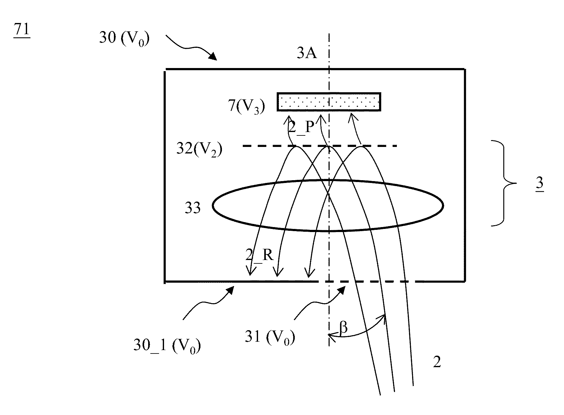
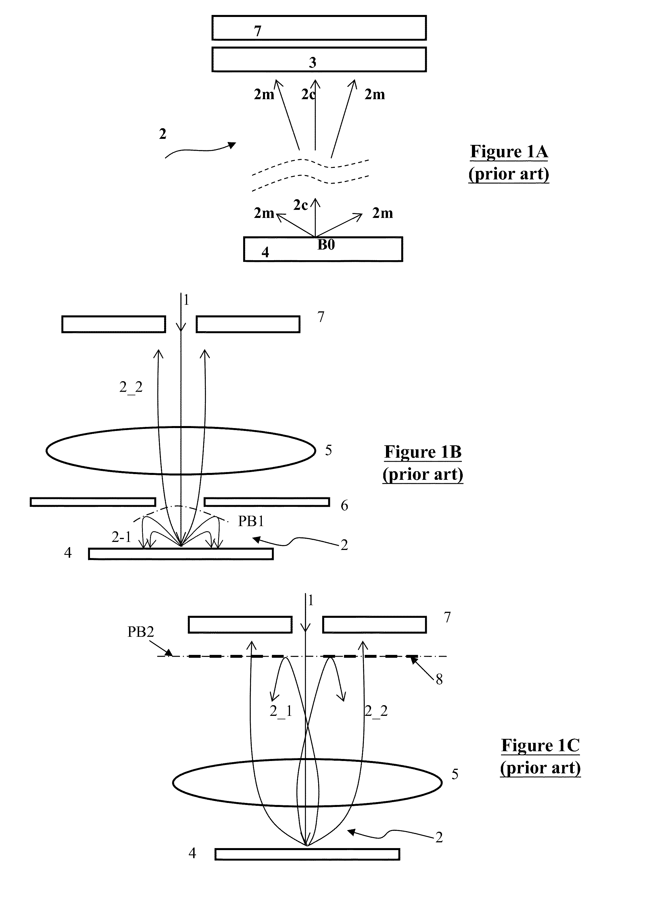
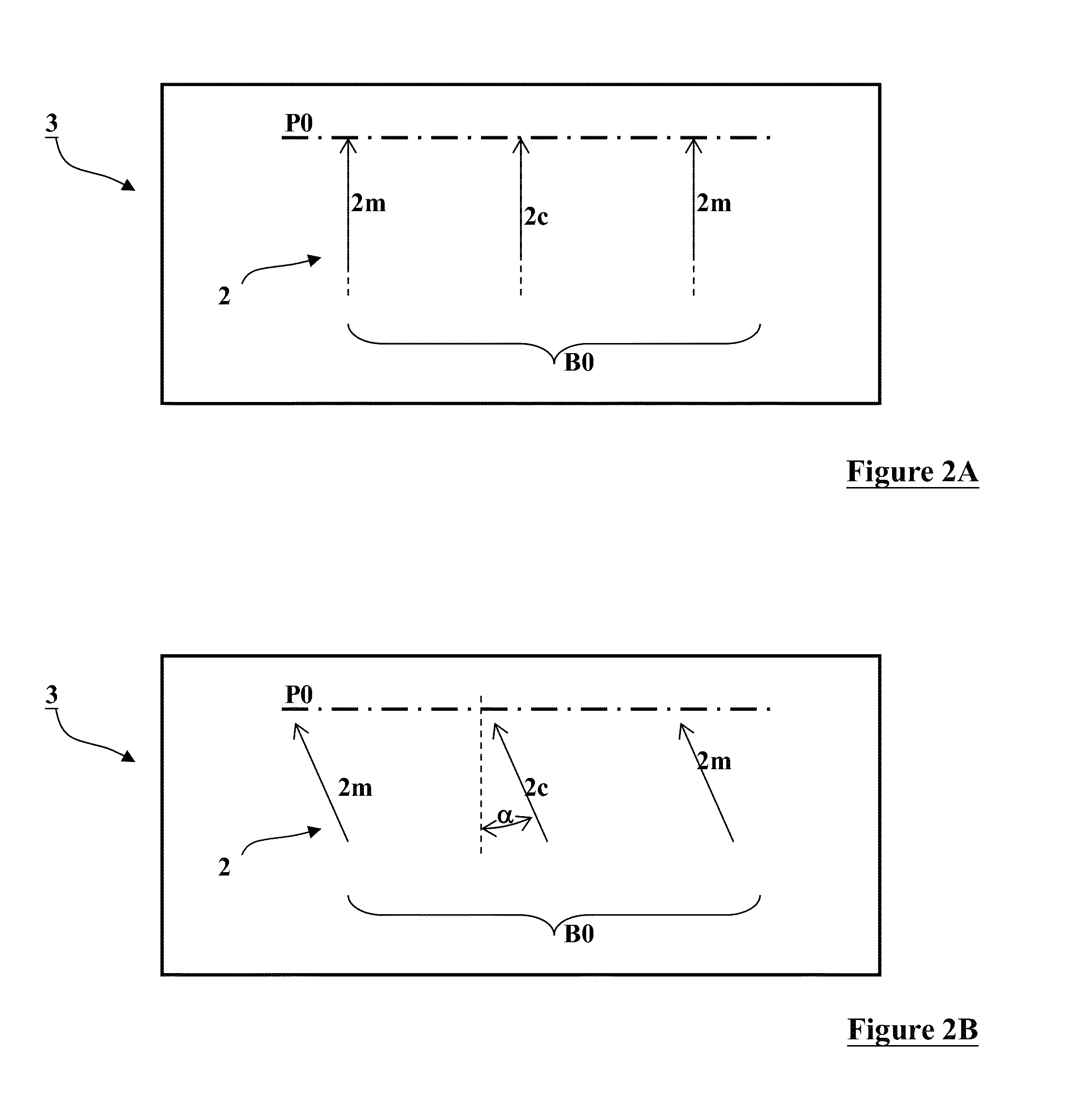
[0041]Various example embodiments of the present invention will now be described more fully with reference to the accompanying drawings in which some example embodiments of the invention are shown. Without limiting the scope of the protection of the present invention, all the description and drawings of the embodiments will exemplarily be referred to an electron beam. However, the embodiments are not be used to limit the present invention to specific charged particles.

[0042]In the drawings, relative dimensions of each component and among every component may be exaggerated for clarity. Within the following description of the drawings the same or like reference numbers refer to the same or like components or entities, and only the differences with respect to the individual embodiments are described.

[0043]Accordingly, while example embodiments of the invention are capable of various modifications and alternative forms, embodiments thereof are shown by way of example in the drawings and...


PUM


Abstract

This invention provides a method for improving performance of a reflective type energy filter for a charged particle beam, which employs a beam-adjusting lens on an entrance side of a potential barrier of the energy filter to make the charged particle beam become a substantially parallel beam to be incident onto the potential barrier. The method makes the energy filter have both a fine energy-discrimination power over a large emission angle spread and a high uniformity of energy-discrimination powers over a large FOV. A LVSEM using this method in the energy filter can obviously improve image contrast. The invention also provides multiple energy-discrimination detection devices formed by using the advantages of the method.

Description

CLAIM OF PRIORITY[0001]This application claims the benefit of priority of U.S. provisional application No. 61 / 823,042 entitled to inventors filed May 14, 2013 and entitled “Energy Filter for Charged Particle Beam Apparatus”, the entire disclosures of which are incorporated herein by reference.FIELD OF THE INVENTION[0002]The invention relates to a charged particle beam device, and more particularly to an energy filter for filtering a charged particle beam in terms of particle energies thereof. The invention also relates to a charged beam apparatus suitable for using such a device, such as an energy-discrimination detection device in a low-voltage scanning electron microscope (LVSEM) for inspecting defects on surfaces of wafers or masks in semiconductor manufacturing industry. However, it would be recognized that the invention has a much broader range of applicability.BACKGROUND OF THE INVENTION[0003]In the field of LVSEM and the related industrial fields which employ the principle of...

Claims


Application Information

Patent Timeline
Patent Type & Authority Patents(United States)
IPC IPC(8): H01J37/12H01J37/05H01J37/244H01J37/26
CPCH01J37/05H01J37/12H01J37/244H01J37/263H01J37/10H01J2237/057H01J2237/12H01J2237/14
Inventor REN, WEIMINGLI, SHUAICHEN, ZHONGWEI
Owner ASML NETHERLANDS BV
Why Eureka
Try Eureka