Security barriers with automated reconnaissance

a security barrier and automated technology, applied in the field of security barriers with automated reconnaissance, can solve the problems of insufficient synergy and practicality of prior art combining security barriers with sensors, and achieve the effects of reducing false alarm rate, reducing cost per unit length, and improving probability of detecting and classifying attempts at intrusion

Active Publication Date: 2015-04-07
KONTEK INDS
View PDF21 Cites 23 Cited by
  • Summary
  • Abstract
  • Description
  • Claims
  • Application Information

AI Technical Summary

Benefits of technology

[0027]Objects and advantages of the present invention include security barriers and security barrier systems that significantly out-perform those of the prior art, and at a lower cost per unit length. This is accomplished by merging together physical barrier structures of different types, and also by integrating these compound physical barriers with electronic security systems to exploit sensor interactions with structural components of the physical barrier. The objects and advantages are also to achieve security barriers that use sensors and artificial intelligence to improve probability of detecting and classifying attempts at intrusion and with a reduced false alarm rate and reduced nuisance alarm rate.
[0028]Further advantages of the present invention will become apparent to ones skilled in the art upon examination of the accompanying drawings and the following detailed description. It is intended that any additional advantages be incorporated herein.
[0029]The various features of the present invention and its preferred embodiments and implementations may also be better understood by referring to the accompanying drawings and the following detailed descr

Problems solved by technology

Prior art had not discovered the benefits and practicality of mounting a fence to a Normandy type barrier, or to a barrier comprising a row of concrete blocks tied together by a chain of steel bars.
And prior art of combining security barriers with sensors had failed to more fully exploit synergistic integration of primary phy

Method used


Image

  • Security barriers with automated reconnaissance
  • Security barriers with automated reconnaissance
  • Security barriers with automated reconnaissance

Examples


embodiment 10

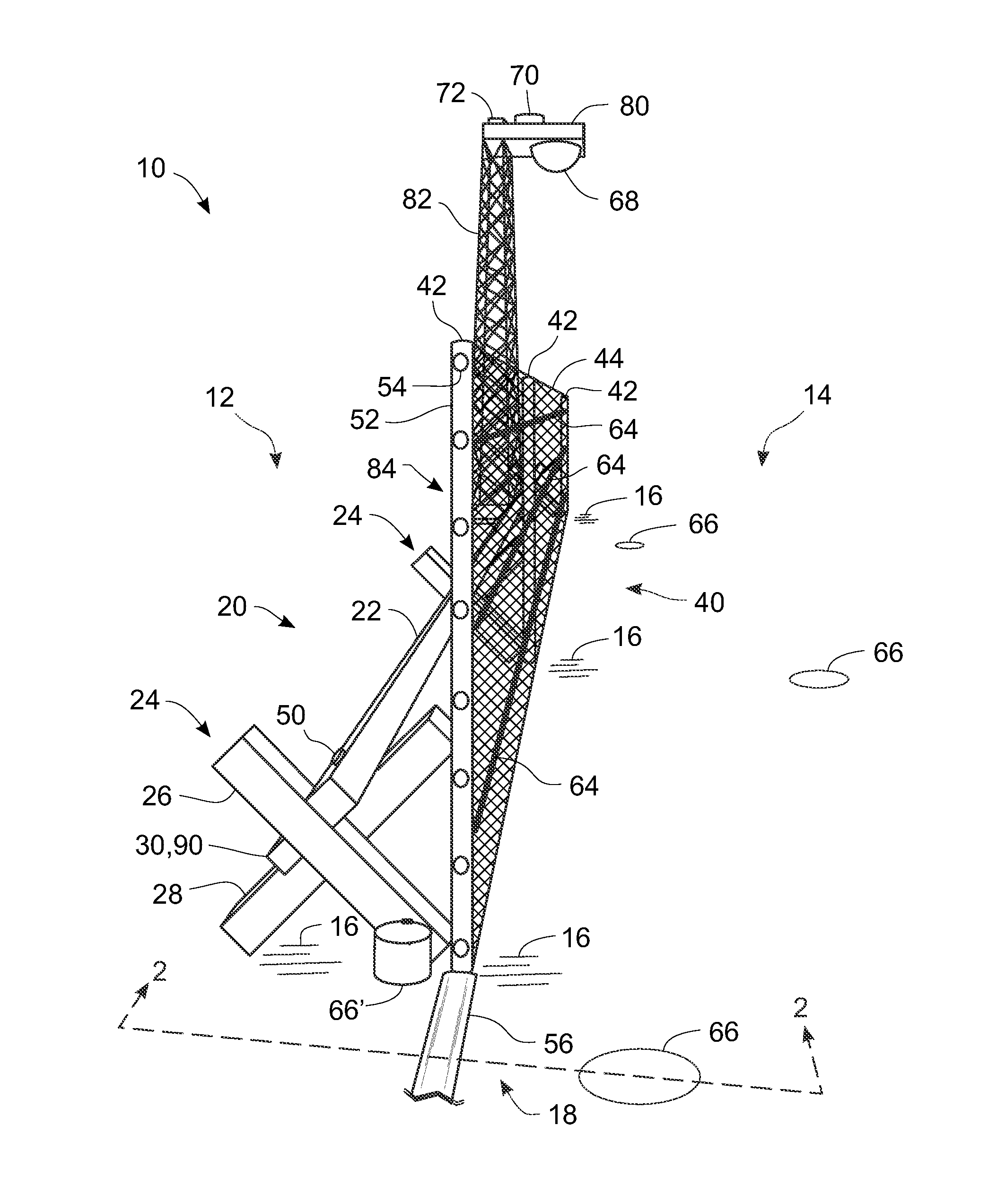
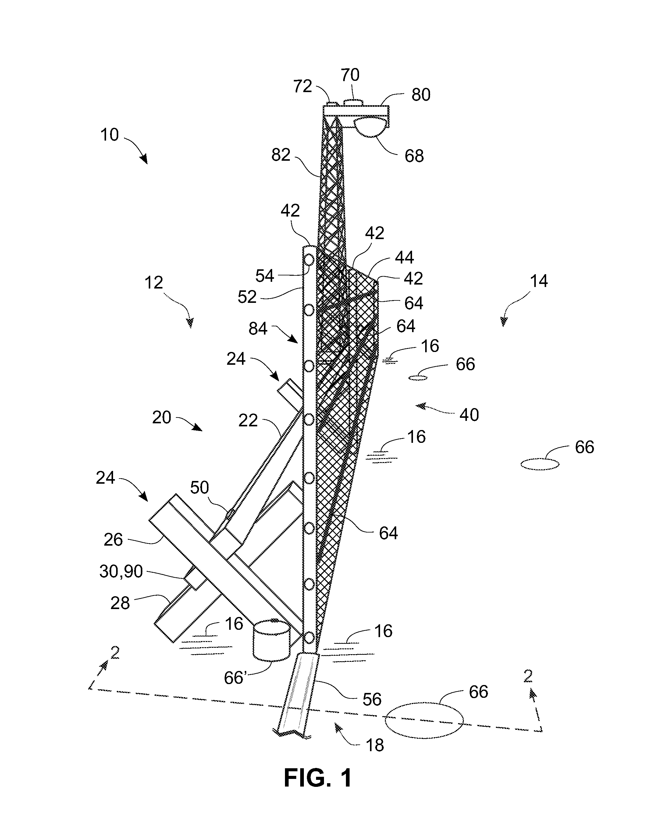
[0068]FIG. 1 provides a reference for discussion regarding how some sensors are mounted to some structures in this and some other of the possible embodiments of the current invention(s). It is an aspect of the current invention(s) that at least some of the sensors should not be used solely as islands of disturbance detection. By that is meant that the present invention(s) make opportunistic use of collections of sensors, some of the same type and / or some of different types, in order to discriminate actual intrusion activities from causes of what could otherwise result in nuisance alarms or in false alarms. This is accomplished by employing sensor mounting structures that facilitate the ability of the sensors to respond to disturbances to which they might not otherwise respond. For example, if a cable sensor 64 was on a fence not attached mechanically to cross-bucks 24 holding a primary beam 22, then it most probably would not respond to disturbances made to the primary beam 22. Simi...

embodiment 300

[0079]FIG. 11 shows a pictorial depiction of a compact embodiment 300′ of a sensor transducer or sensor subsystem 310′. What is shown is a sensor module 310′ with a portion of its communications cable or other connection medium 340′ extending out of a side of the module 310′. The medium 340′ could represent a wireless link to a remote receiver or transceiver.

[0080]FIG. 12 shows one representation of one embodiment of one form of learning machine that might be practiced in implementing some of the embodiments of the current invention(s). Such learning machines would be processed by any of the computers 200 or 300, or any of the computing engines 210 or 210′, shown in FIG. 9, which is to say they could be processed by any of the computers 160, 160′, 170, and / or 180 shown in FIG. 8. What is shown in FIG. 12 is an example of an artificial neural network 400) having a particular structure, but other structures would also fall within the scope of the current invention(s) and claims. These...

embodiment 500

[0081]FIG. 13 shows a two-step process embodiment 500 of simulating neuron activation in each layer of an artificial neural network. In the first step 510 and for the second layer, variable “z(2)” is a vector of values calculated as the product of the transpose of a matrix θ(1) of parameter values for the first layer and a vector “x” of input values. The symbol “T” in the figure stands for the transpose operator. In the first step 510 and for the subsequent j'th layers, variable)“z(j)” is a vector of values calculated as the product of the transpose of a matrix θ(j-1) of parameter values for the “j−1”th layer and a vector “a(j-1)” of activation values of that preceding layer (i.e. of the “j−1”th layer). In the second step 520, activation values a(z) are calculated as a function of z using the logistic function g(z) which is also called a sigmoid function. One skilled in the art of artificial neural networks will recognize that other choices exist for activation functions without dev...


PUM


Abstract

An intrusion delaying barrier includes primary and secondary physical structures and can be instrumented with multiple sensors incorporated into an electronic monitoring and alarm system. Such an instrumented intrusion delaying barrier may be used as a perimeter intrusion defense and assessment system (PIDAS). Problems with not providing effective delay to breaches by intentional intruders and/or terrorists who would otherwise evade detection are solved by attaching the secondary structures to the primary structure, and attaching at least some of the sensors to the secondary structures. By having multiple sensors of various types physically interconnected serves to enable sensors on different parts of the overall structure to respond to common disturbances and thereby provide effective corroboration that a disturbance is not merely a nuisance or false alarm. Use of a machine learning network such as a neural network exploits such corroboration.

Description

STATEMENT REGARDING FEDERALLY SPONSORED RESEARCH OR DEVELOPMENT[0001]This invention was made under a CRADA (SC10 / 01775.00) between Kontek Industries, Inc. (along with its subsidiary, Stonewater Control Systems, Inc.) and Sandia National Laboratories, operated for the United States Department of Energy. The government has certain rights in this invention.CROSS-REFERENCE TO RELATED APPLICATIONS[0002]This application relates to five and co-owned Non-provisional patent applications filed simultaneously to one-another on Sep. 8, 2010 as follows: 1) titled “Security Systems Having Communication Paths in Tunnels of Barrier Modules and Armored Building Modules”, application Ser. No. 12 / 877,670; 2) titled “Security Systems with Adaptive Subsystems Networked through Barrier Modules and Armored Building Modules”, application Ser. No. 12 / 877,728; 3) titled “Diversity Networks and Methods for Secure Communications”, application Ser. No. 12 / 877,754; 4) titled “Autonomous and Federated Sensory Sub...

Claims


Application Information

Patent Timeline
IPC IPC(8): G08B13/00G08B13/12
CPCG08B13/122G08B13/12
Inventor MCLAUGHLIN, JAMES O.BAIRD, ADAM D.TULLIS, BARCLAY J.NOLTE, ROGER ALLEN
Owner KONTEK INDS
Why Eureka
Try Eureka