Method of using shaped compressed pellets in treating a well

a compressed pellet and well technology, applied in the field of shaped compressed pellets, can solve the problems of reducing the productivity of wells, reducing the permeability of wells, and restricting the production piping and the potential plugging of flow paths including reservoir flow paths

Active Publication Date: 2015-04-21
BAKER HUGHES INC
View PDF67 Cites 18 Cited by
  • Summary
  • Abstract
  • Description
  • Claims
  • Application Information

AI Technical Summary

Benefits of technology

[0011]Shaped compressed pellets formed from a composite of a well treatment agent in a matrix may be used to slowly and continuously release the well treatment agent into a targeted area in a well.
[0012]A major advantage of the shaped pellets is that they typically do not require use of any specialized equipment. They are especially useful in the treatment of production wells where traditional mechanical means are unable to reach.
[0013]The shaped pellets may be dropped directly into the well from the well head. When introduced into production tubing within an oil or gas well, the shaped pellets easily flow past obstructions and through well deviations. Continuous release of the well treatment agent with the production fluid protects the tubular and the surface equipment from unwanted deposits which may be formed in the tubular or surface equipment. The high specific gravity of the shaped pellets allows them to pass by gravity into and through production tubing.
[0014]The shaped pellets are especially useful when introduced into horizontal or deviated wells since they easily pass through restrictions in the wellbore and flow into low points of the horizontal well or past obstruction in a deviated well.
[0015]When shaped as spheres, the pellets are able to readily roll over obstructions within the tubing and thru well deviations to effectively place the well treatment agent in close proximity to the targeted area. The spheres are especially useful in delivering well treatment agents in wells having deviations ranging from 45° to 89° or in wells with multiple deviations such as “S” shaped completions.

Problems solved by technology

It is well known that unwanted deposits can precipitate from saturated oilfield waters in an oil or gas well leading to a restriction in the production piping and the potential plugging of the flow path including reservoir flow paths.
The formation and deposition of such unwanted contaminants decrease permeability of the subterranean formation, reduce well productivity, and, in some cases, may completely block the well tubing.
Wire lines and coil tubing have limited effectiveness, however, when the tubular being treated is deviated, as in a horizontal well or “S” shaped configuration.
The flexibility of the wire and coil tubing make it difficult to push a long distance past a severe deviation or multiple deviations.
This technique requires large volumes of treatment and flush fluid in horizontal wells with a large area of perforated interval.
Such treatment methods are typically inefficient in horizontal wells because it is difficult to ensure the treatment is delivered to all the intended area.
The flush and chemical additive often required large pumps and holding tanks which can add significant costs to the application.
This technique is effective in its intended function but is expensive and requires specialized equipment to install.
Further, capillary tubing may not be able to extend to great depths if the deviation angle is severe or the piping extends far beyond the bend.
While solid additives have been added to the well during the completion stage, this technique has only been proven to be an effective delivery method in new wells when the opportunity to spot the chemical additive is available.

Method used


Image

  • Method of using shaped compressed pellets in treating a well
  • Method of using shaped compressed pellets in treating a well
  • Method of using shaped compressed pellets in treating a well

Examples


example 1

[0062]About 800 g of 10 / 50 mesh diatomaceous earth (Celite MP-79) absorbent was added into a mixing bowl. A paddle mixer blade was attached and liquid organophosphate (DEQUEST® 2000 phosphate, a product of Dequest AG) was added to the mixing bowl at a rate in which the liquid was readily absorbed, and the liquid did not puddle. After all of the liquid was added, mixing was continued until a homogenous blend was produced. The blend was then dried at 225 F until the percent moisture of the resulting product was less than 3%. The composite thus prepared contained 25 percent by weight of organophosphate scale inhibitor.

[0063]To the composite was then added a binder of an epoxy resin (A), phenolic resin (B) and polyvinyl alcohol (C). The mixture contained about 50 percent by weight of the resin. The mixture was then compressed under a pressure of about 250 psi for about 1 minute in a mold to render a cylindrical pellet resembling a hockey puck having a diameter of about 1 inch and a thic...

example 2

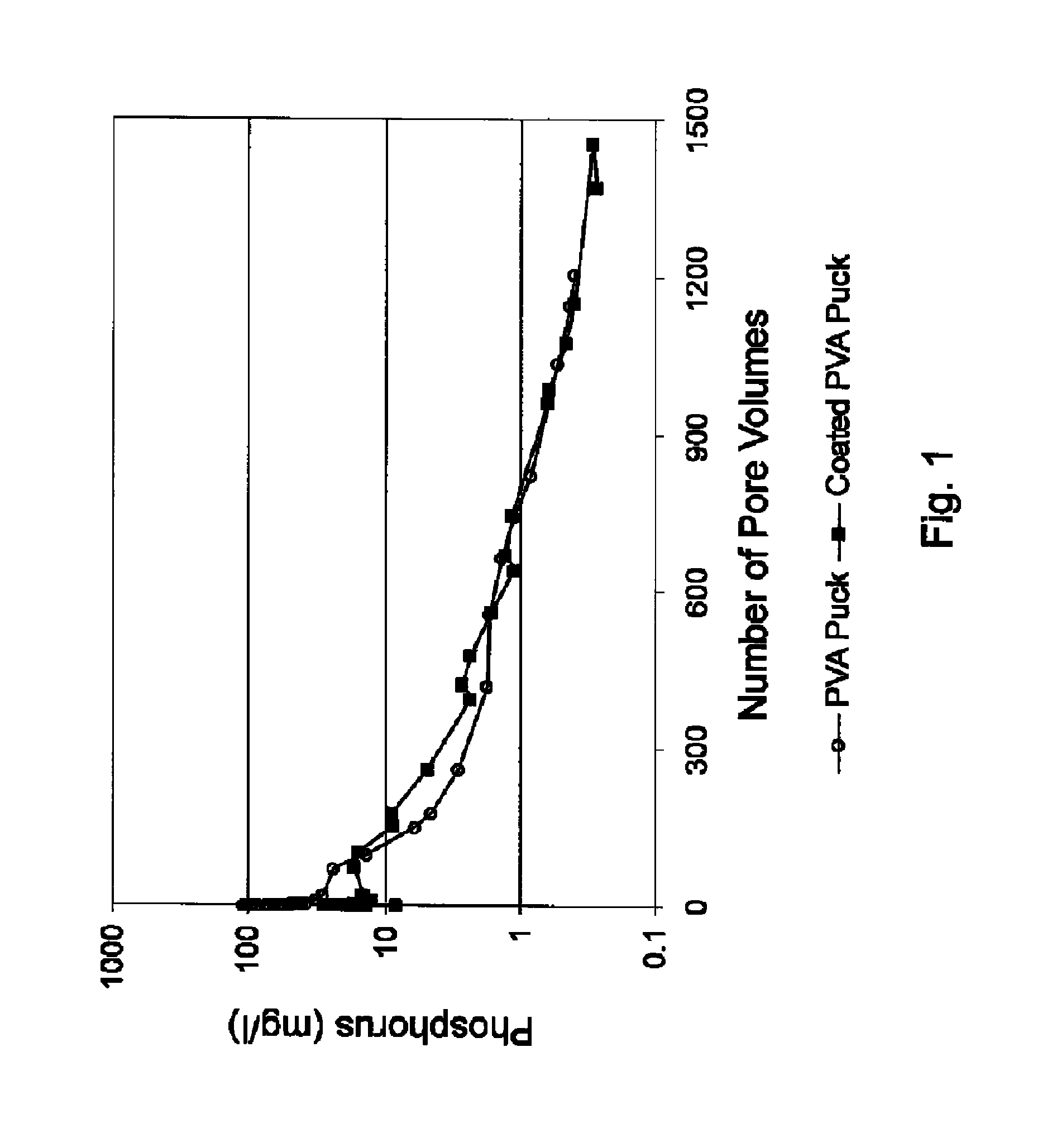
[0064]The elution characteristics of Puck C and Puck D were then determined by packing approximately 440 grams 20 / 40 Ottawa white frac sand and 3 pieces of the pucks into a 30 cm length stainless steel column (ID=3.48 cm). The pore volume of the column was approximately 80 milliliters. The column was eluted with a synthetic brine (0.025 mol / L CaCl2, 0.015 mol / L NaHCO3, 1 mol / L NaCl, sparged with 100% CO2) at 60° C. at a flow rate of 270 ml / hour. The effluent solution was collected and analyzed for phosphorus and calcium concentration to obtain the inhibitor flow back curve, set forth in FIG. 1. As illustrated in FIG. 1, the concentration of phosphorus in the effluent gradually decreased as synthetic brine was pumped into the column. After 1200 pore volumes of return flow, the concentration of effluent phosphorus remained approximately 0.4 ppm. There was no significant difference found between the phosphorus return curves of Puck (C) and Puck (D). The data demonstrates the ease that ...

example 3

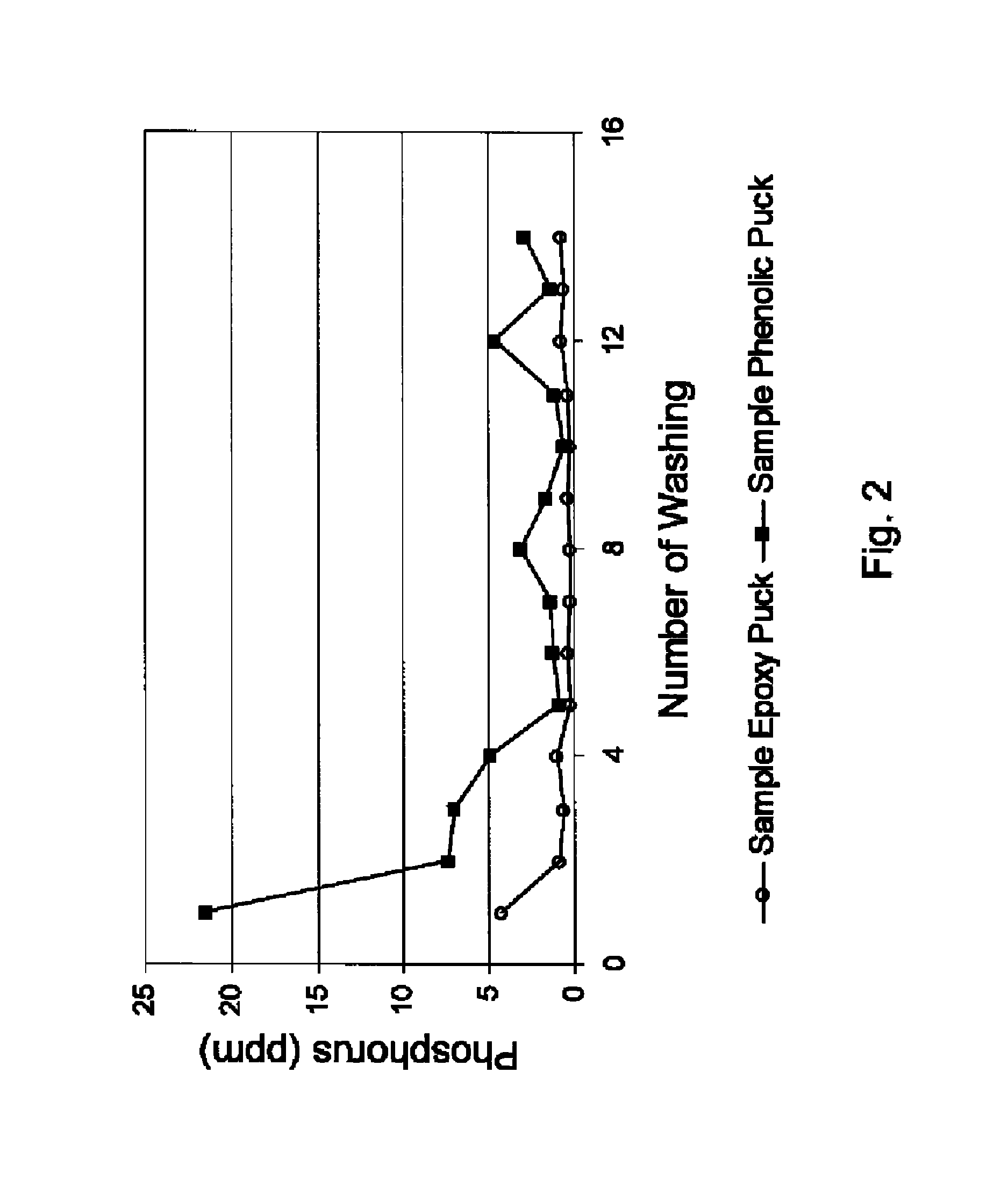
[0065]Puck (A) and Puck (B) were mixed with 500 ml of water. After 30 minutes, the supernatant was removed and the concentration of phosphorus in the supernatant was measured by (ICP) spectrophotometer. The test was repeated 14 times. The amount of residual phosphorous in the supernatant, illustrated as the static breaker test, is illustrated in FIG. 2. FIG. 2 demonstrates that the concentration of phosphorus in the effluent concentration of Puck (B) was higher than that of sample Puck (A) after washing with tap water.


PUM

PropertyMeasurementUnit
diameteraaaaaaaaaa
specific gravityaaaaaaaaaa
diameteraaaaaaaaaa

Abstract

Shaped particulates which have been compressed from a composite of a well treatment agent and adsorbent in a matrix may be introduced into horizontal or deviated oil or gas wells. The well treatment agent of the shaped pellets may be used to prevent and / or control the formation of deposits in a production well.

Description

FIELD OF THE INVENTION[0001]The invention relates to shaped compressed pellets formed from a composite of a well treatment agent in a matrix which are useful to inhibit and / or control the formation of unwanted deposits in a well.BACKGROUND OF THE INVENTION[0002]Oilfield fluids (e.g., oil, gas, and water) are generally complex mixtures of aliphatic hydrocarbons, aromatics, hetero-atomic molecules, anionic and cationic salts, acids, sands, silts, clays and a vast array of other components. The nature of these fluids, combined with the severe conditions of heat, pressure, and turbulence to which they are often subjected, are contributing factors to the formation and deposition of unwanted contaminants, such as scales, salts, paraffins, corrosion, bacteria and asphaltenes in oil and / or gas production wells.[0003]It is well known that unwanted deposits can precipitate from saturated oilfield waters in an oil or gas well leading to a restriction in the production piping and the potential ...

Claims


Application Information

Patent Timeline
Patent Type & Authority Patents(United States)
IPC IPC(8): E21B37/06C09K8/52C09K8/524C09K8/536
CPCC09K8/524C09K8/536E21B37/06
Inventor DARBY, JOHN GREGORYGUPTA, D. V. SATYANARAYANASHEN, DONG
Owner BAKER HUGHES INC
Why Eureka
Try Eureka