Variable cam timing system and method

a timing system and variable cam technology, applied in the direction of yielding couplings, valve arrangements, couplings, etc., can solve the problems of increasing noise, vibration, harshness, etc., reducing customer satisfaction and component longevity, and increasing the manufacturing cost of the locking device disclosed in u.s. pat. no. 5,823,152, so as to increase the engine power output, reduce emissions, and increase combustion efficiency

Active Publication Date: 2015-05-05
FORD GLOBAL TECH LLC
View PDF8 Cites 9 Cited by
  • Summary
  • Abstract
  • Description
  • Claims
  • Application Information

AI Technical Summary

Benefits of technology

[0002]Variable cam timing (VCT) is used in engines to advance or retard intake and / or exhaust valve timing. Consequently, intake and / or exhaust valve timing may be adjusted based on engine operating conditions to increase combustion efficiency and decrease emissions, if desired. Additionally, engine power output may be increased across a wider range of engine operating conditions.
[0004]The Inventors have recognized several drawbacks with the valve timing control apparatus disclosed in U.S. Pat. No. 5,823,152. Manufacturing the locking device disclosed in U.S. Pat. No. 5,823,152 may be costly due to the small tolerances of the tapered locking member and the tapered bore. Additionally, the tapered locking member may become disengaged, due to air pressure, for example. Consequently, the partially disengaged member may move back and forth (e.g., rattle) in an engaging bore receiving the locking member. As a result, the noise, vibration, and harshness (NVH) in the vehicle may be increased, thereby decreasing customer satisfaction and component longevity. Furthermore, the locking member disclosed in U.S. Pat. No. 5,823,152 may become stuck in the engaging bore due to the tapered matting. As a result, phase control functionality may be delayed or inhibited, thereby decreasing combustion efficiency and increasing emissions.
[0007]When the housing is spaced away from the vane in a locked configuration the vibration caused by the contact between the vane and the housing is substantially reduced (e.g., eliminated). In this way, NVH in the engine is reduced, thereby increasing customer satisfaction and component longevity when compared to VCT systems having the housing in direct contact with a vane in a locked configuration.
[0008]In one example, the backlash may be less than the gap between the housing and the vane. In this way, the movement of the locking pin in the locking pin recess does not cause the vane to contact the housing in a locked configuration. As a result, NVH is reduced.

Problems solved by technology

Manufacturing the locking device disclosed in U.S. Pat. No. 5,823,152 may be costly due to the small tolerances of the tapered locking member and the tapered bore.
As a result, the noise, vibration, and harshness (NVH) in the vehicle may be increased, thereby decreasing customer satisfaction and component longevity.
Furthermore, the locking member disclosed in U.S. Pat. No. 5,823,152 may become stuck in the engaging bore due to the tapered matting.
As a result, phase control functionality may be delayed or inhibited, thereby decreasing combustion efficiency and increasing emissions.

Method used


Image

  • Variable cam timing system and method
  • Variable cam timing system and method
  • Variable cam timing system and method

Examples


Embodiment Construction

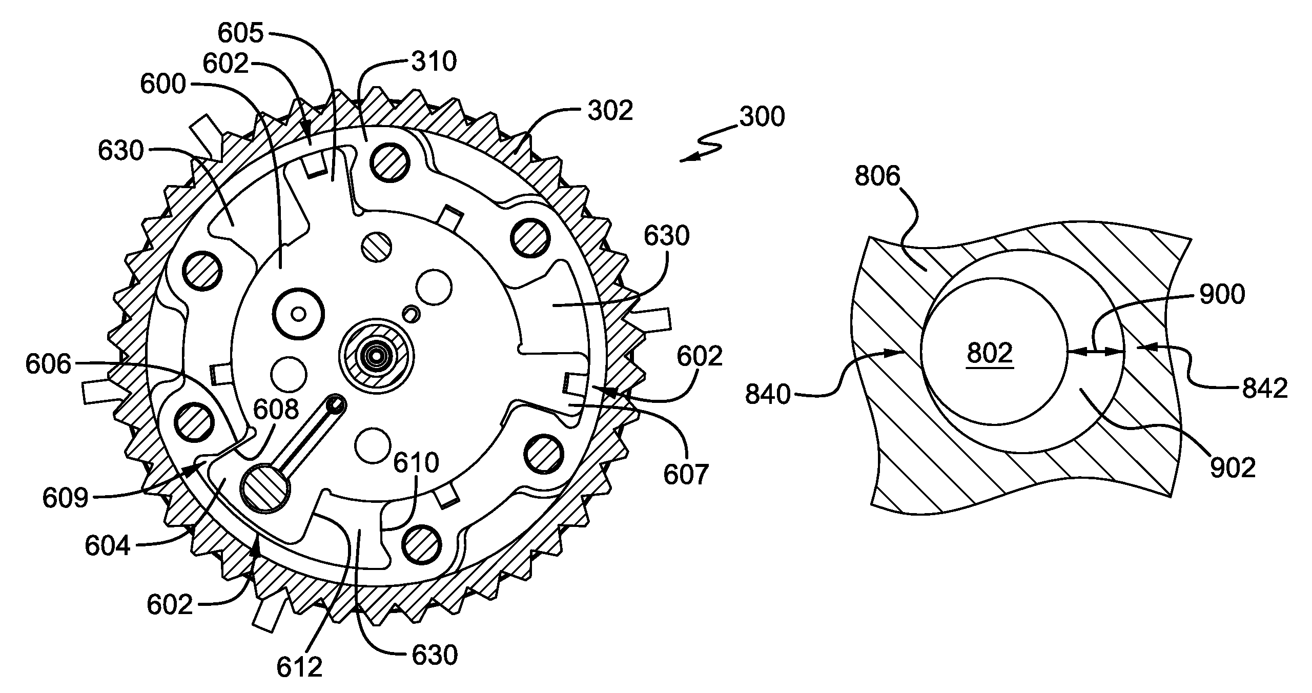
[0016]A locking mechanism in a variable cam timing (VCT) system is disclosed herein. The locking mechanism includes a locking pin and locking pin recess having backlash. The locking mechanism also includes a vane and housing, the relative position of the vane and the housing may be adjusted to alter cam timing. In a locked configuration when the locking pin is mated with the locking pin recess, the vane is circumferentially spaced away from the housing in a hydraulic chamber. When the housing is spaced away from the vane, the likelihood of the vane contacting or striking the housing during locking is reduced (e.g., eliminated). Consequently, noise, vibration, and harshness (NVH) in the VCT system is reduced which increases customer satisfaction and decreases component wear. This spacing also enables the tolerances of the locking pin and locking pin recess to be increased if desired, thereby decreasing manufacturing costs.

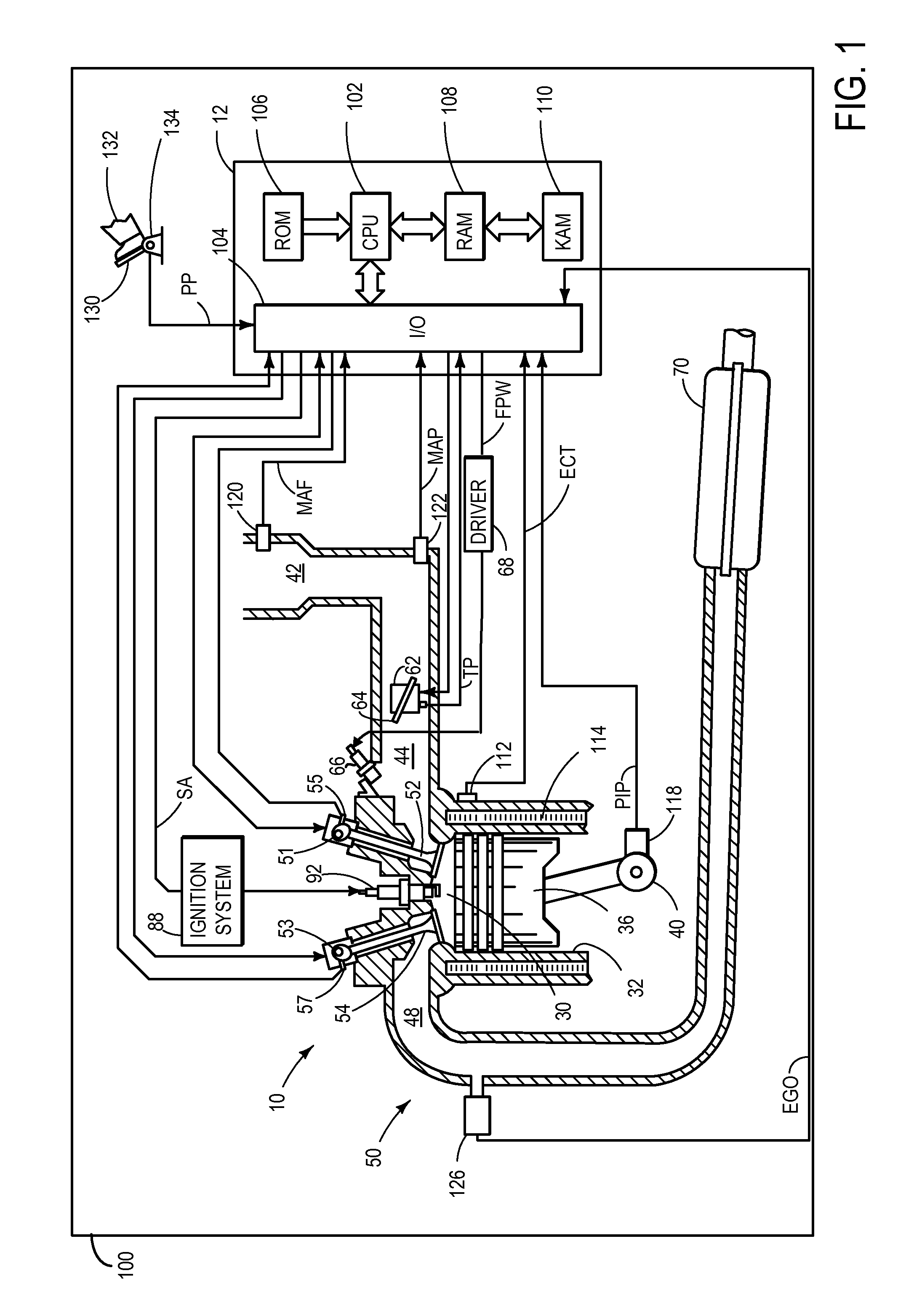
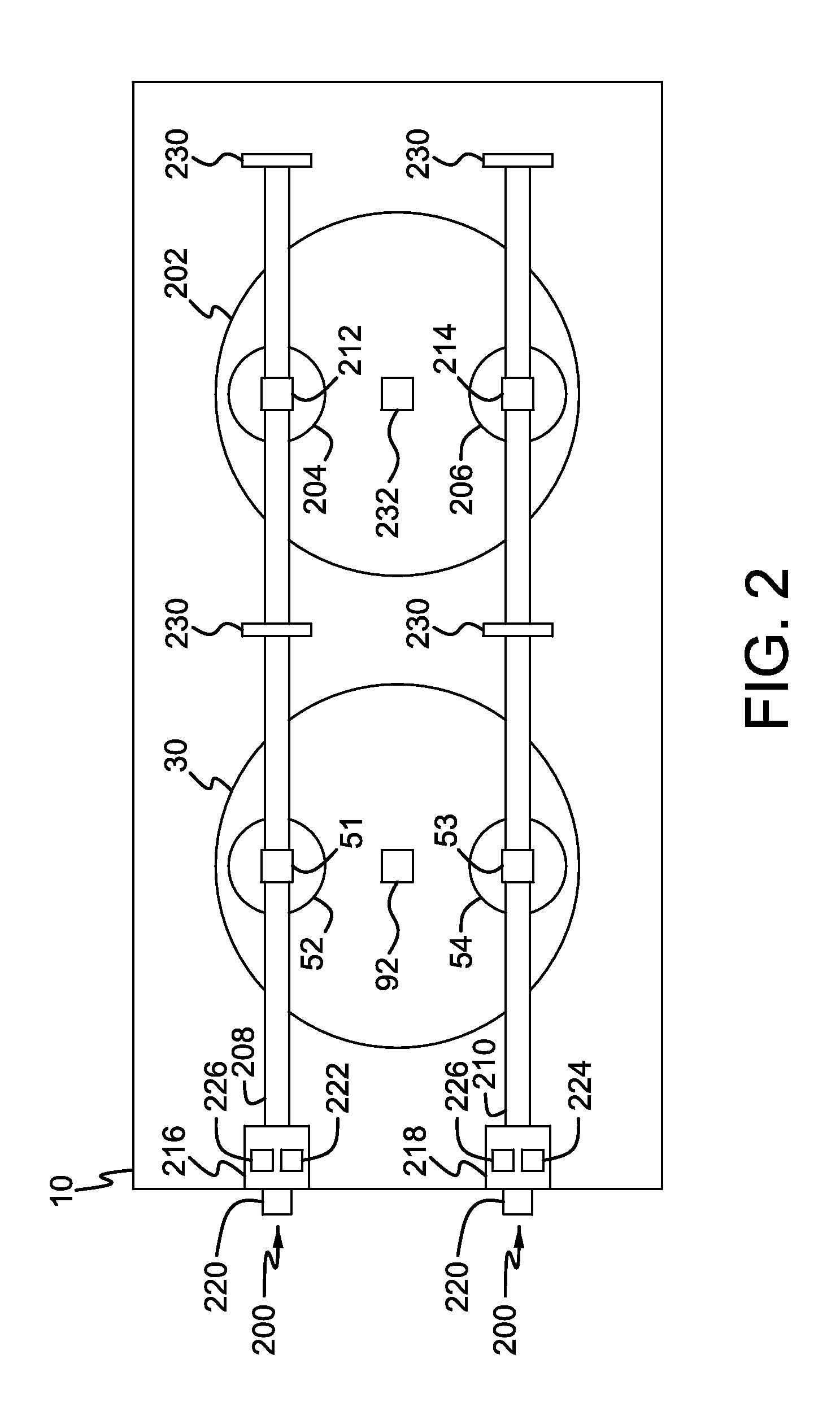
[0017]FIGS. 1 and 2 show schematic depictions of an internal c...


PUM


Abstract

A phase control apparatus in a variable cam timing (VCT) system of an engine is described herein. The phase control apparatus includes a locking pin coupled to a vane, the locking pin extending into a locking pin recess in a cover plate in a locked configuration, the locking pin and locking pin recess having a backlash and a housing at least partially enclosing the vane and spaced away from the vane forming a gap in the locked configuration.

Description

FIELD[0001]The present disclosure relates to a variable cam timing system including a locking mechanism.BACKGROUND AND SUMMARY[0002]Variable cam timing (VCT) is used in engines to advance or retard intake and / or exhaust valve timing. Consequently, intake and / or exhaust valve timing may be adjusted based on engine operating conditions to increase combustion efficiency and decrease emissions, if desired. Additionally, engine power output may be increased across a wider range of engine operating conditions.[0003]Locking mechanisms in VCT systems have been developed to lock the VCT system in a desired base configuration when there is insufficient oil pressure to operate the VCT system. For example, U.S. Pat. No. 5,823,152 discloses an angular phase control apparatus for an engine including a tapered locking member configured to mate with an engaging bore to lock the apparatus in a desired angular position.[0004]The Inventors have recognized several drawbacks with the valve timing contro...

Claims


Application Information

Patent Timeline
Patent Type & Authority Patents(United States)
IPC IPC(8): F01L1/34F01L1/344
CPCF01L1/344F01L1/3442F01L2001/34456F01L2001/34469
Inventor MOETAKEF, MOHAMMAD ALIHANSHAW, JAMIE CHARLESKRIDNER, WESLEYFESTAG, GEORGPOE, STEVE
Owner FORD GLOBAL TECH LLC
Why Eureka
Try Eureka