Implant for influencing blood flow

a technology of blood flow and implants, applied in blood vessels, medical science, textiles and papermaking, etc., can solve problems such as fatal risks, spirals may be flushed out, and patients may be affected

Active Publication Date: 2015-05-19
PHENOX
View PDF19 Cites 12 Cited by
  • Summary
  • Abstract
  • Description
  • Claims
  • Application Information

AI Technical Summary

Benefits of technology

[0045]A suitably designed retaining element with two fixing elements may have both fixing elements connected to one and the same guide wire and arranged at a defined distance away from each other so that it is ensured the implant of a given length undergoes a defined elongation and tensioning. In this manner any excessive elongation is ruled out and the restoring forces that are exerted after the implant is liberated within the vessel can be fully effective. As an alternative the fixing elements may also be attached to two separate guide wires which enable the implant to be adjusted or elongated by the attending physician or by means of a suitably designed securing device. The second guide wire may also be designed in the form of a guide tube.

Problems solved by technology

Arteriovenous malformation may significantly impair a patient and may even result in fatal risks.
Nevertheless, this treatment approach only suits aneurysms that have a relatively narrow access to the vessel system, so-called aciniform aneurysms.
In the event of vessel protuberances having a wide access to the blood vessel there is a risk that the implanted spirals may be flushed out and cause damage to other areas of the vascular system.
On the one hand, this concerns the wide-meshed structure which does not prevent blood from entering the aneurysm.
So if the occlusion means does not occupy the aneurysm space adequately the pressure exerted on the vessel wall remains undiminished.
An after-treatment in this case may be difficult, however, because the stent will obstruct access to the aneurysm and impair the placement of additional occlusion means.
Another drawback is that the stent cannot be adapted to its placement site.
It thus follows that this type of stent is only of limited use when it comes to meet the requirements in question even if it has been selected especially for the envisaged purpose.
A problem encountered with these stents of circular braiding design is that the small-diameter loose ends existing on the free ends may have traumatic effects.
However, the U-shaped connecting links are prone to cause stresses and thus lead to deformation of the stent.
Another problematic aspect associated with stents or implants made of wire braiding is their manufacture.

Method used


Image

  • Implant for influencing blood flow
  • Implant for influencing blood flow
  • Implant for influencing blood flow

Examples


Embodiment Construction

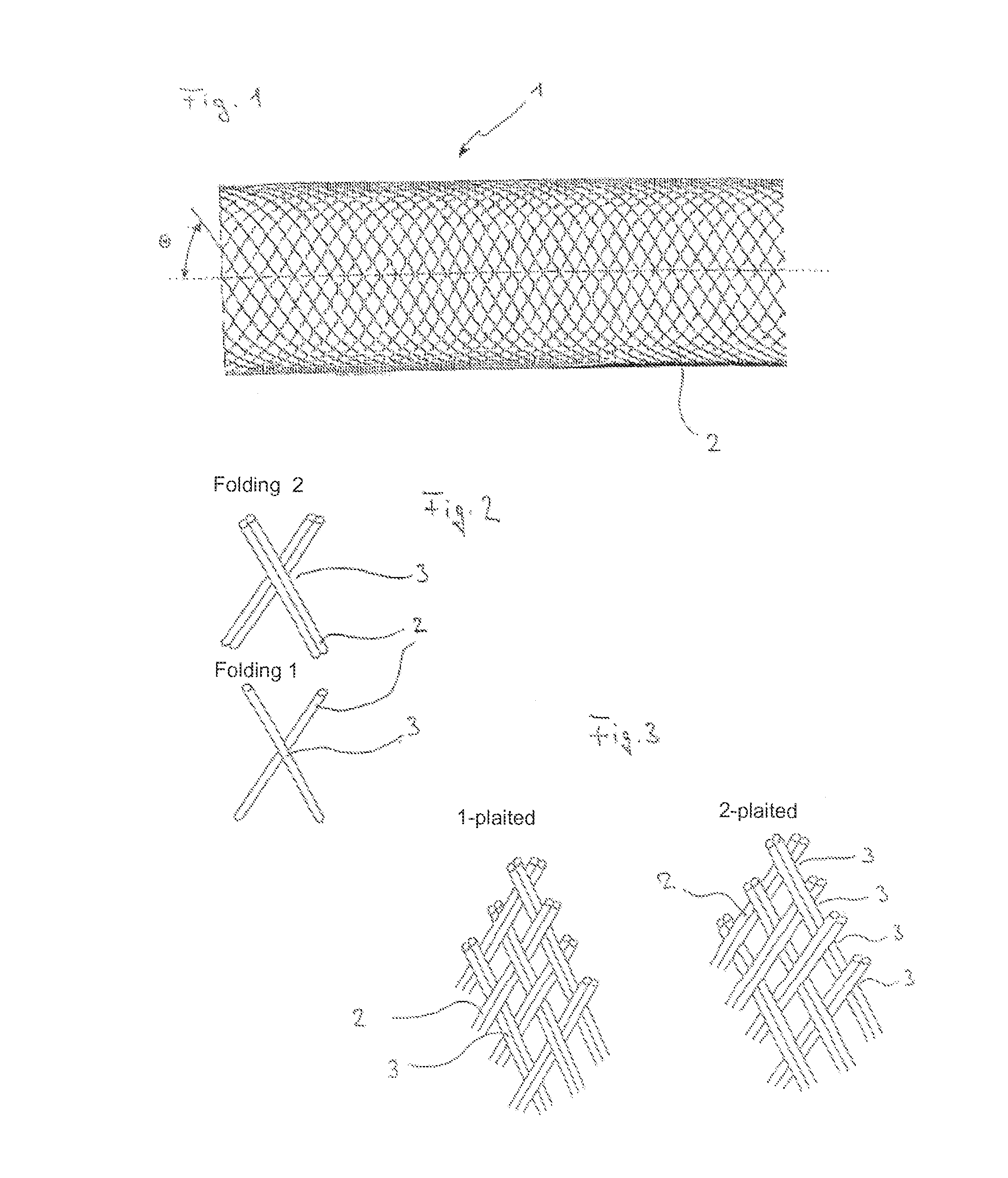
[0060]FIG. 1 shows the braid structure of an inventive implant 1 consisting of individual filaments 2 intertwined with each other. In the example shown the individual filaments intersect at an angle of approx. 120° with the open side of the angle pointing to the open ends of the circular braiding. The illustration shows the braid in a slightly stretched / elongated state, i.e. the diameter is reduced.

[0061]The angle Theta denotes the braid angle in relation to the longitudinal axis, said angle may amount up to 80° in unstretched condition and when nominal diameter has been reached. When the braiding is in elongated position inside the catheter angle Theta may reduce to approx. 7°.

[0062]It is to be understood that the nominal diameter of the circular braiding will match the lumen of the target vessel at the location where treatment takes place.

[0063]The braid is manufactured on a conventional braiding machine in the form of an endless braid structure. Braiding is performed on a mandrel...


PUM


Abstract

An implant for blood vessels, in particular to influence the flow of blood in the area of arteriovenous malformations. The implant has a wall comprising individual filaments combined so as to form a circular braiding, the circular braiding being positioned in elongated form and with a reduced diameter in an insertion catheter and expanding at the placement site thus adapting to the vessel diameter and increasing its braiding density.

Description

BACKGROUND[0001]1. Field of the Invention[0002]The invention relates to an implant for blood vessels that has a wall comprising individual filaments combined to form a circular braiding. The implant shall in particular serve to influence the flow of blood in the area of arteriovenous malformations, for example fistulas and aneurysms. It may also be used in the treatment of ischemic strokes, for example to restore, increase or maintain the blood flow. The implant may be designed so as to be recoverable.[0003]2. Related Art[0004]Arteriovenous malformation may significantly impair a patient and may even result in fatal risks. In particular, this applies to arteriovenous fistulas and aneurysms, especially when these are found to exist in the cerebral region. Normally, attempts are made to close off such malformations by implants which, as a rule, are placed in position by endovascular techniques with the help of catheters.[0005]Especially when treating aneurysms implanting platinum spir...

Claims


Application Information

Patent Timeline
Patent Type & Authority Patents(United States)
IPC IPC(8): A61F2/82A61F2/966A61F2/90A61F2/95
CPCA61F2002/823A61F2/90A61F2250/0039A61F2250/0015A61F2002/9505D04C1/06D10B2509/06
Inventor HANNES, RALFMONSTADT, HERMANNSALEN, MANUEL
Owner PHENOX
Why Eureka
Try Eureka