Radiation generating tube and radiation generating apparatus using the same

a radiation generating apparatus and generating tube technology, applied in the field of radiation generating tubes, can solve problems such as the ability to improve the voltage withstanding capacity, and achieve the effect of high voltage withstanding capability

Active Publication Date: 2015-06-02
CANON KK
View PDF5 Cites 6 Cited by
  • Summary
  • Abstract
  • Description
  • Claims
  • Application Information

AI Technical Summary

Benefits of technology

[0010]According to the present invention: the electrical potential defining member is disposed at an intermediate portion of the tubular side wall of the radiation generating tube in the axis direction; the electrical potential defining member is electrically connected to the electrical potential defining unit via the electrical resistance member or the inductor; and the potential of the electrical potential defining member is defined to be higher potential than that of the cathode and to be lower than potential of the anode. Since the electrical resistance member or the inductor is disposed between the electrical potential defining member and the electrical potential defining unit, electrical discharge less easily occurs between the intermediate electrode and the focusing electrode or between the intermediate electrode and the electron source. Even when electrical discharge occurs between the intermediate electrode and the focusing electrode, or between the intermediate electrode and the electron source, the discharge current which flows into the focusing electrode or the electron source from the electrical potential defining member may be reduced. Therefore, it is possible to prevent occurrence of secondary electrical discharge which may be caused by electrical discharge between the intermediate electrode and the focusing electrode, or between the intermediate electrode and the electron source. Therefore, a radiation generating tube of high voltage withstanding capability and radiation generating apparatus capable of performing high energy output are provided.

Problems solved by technology

Such a transmission radiation generating tube and a reflective radiation generating tube have had a problem about how to improve their voltage withstanding capability.
If, however, further improvement in voltage withstanding capability is desired in these techniques described above, the following problems may arise.

Method used


Image

  • Radiation generating tube and radiation generating apparatus using the same
  • Radiation generating tube and radiation generating apparatus using the same
  • Radiation generating tube and radiation generating apparatus using the same

Examples


first example

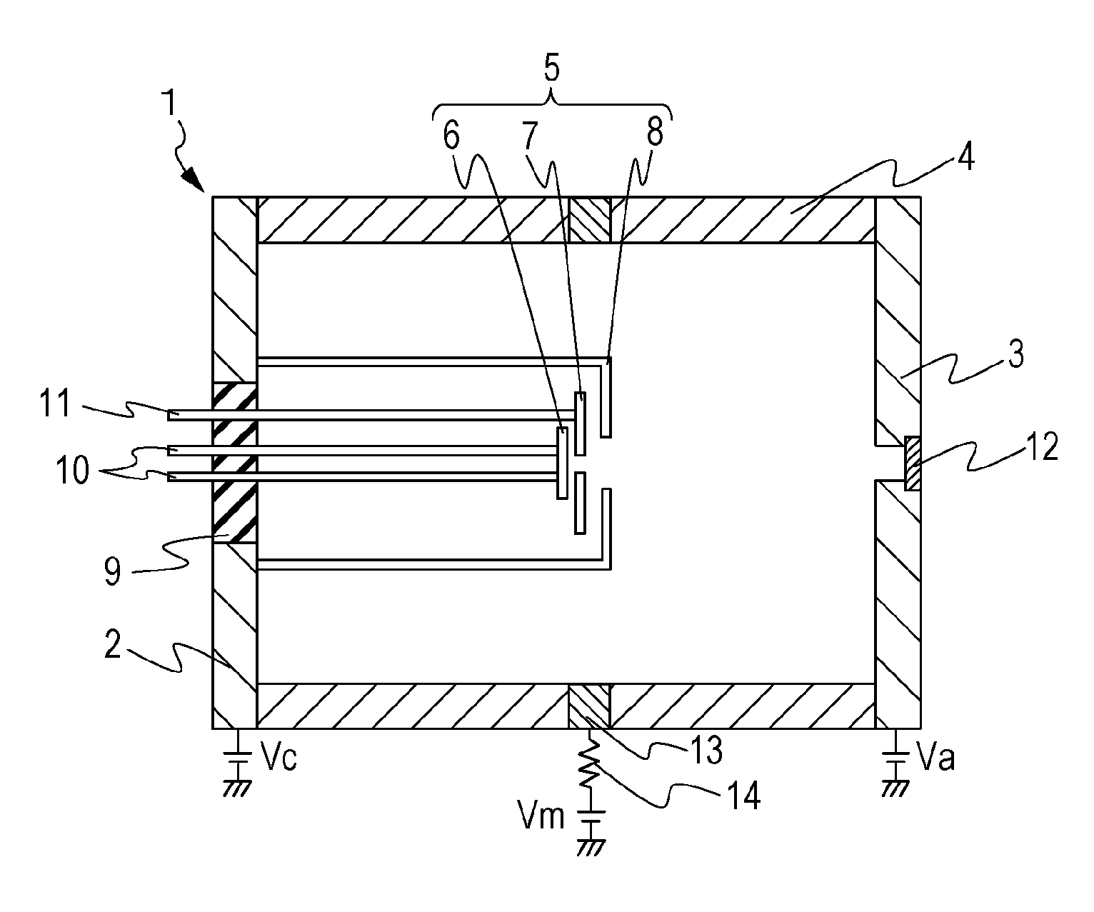
[0037]A first example, which is one of the exemplary configurations described above, will be described with reference to FIG. 1A. FIG. 1A is a schematic cross-sectional view of a radiation generating tube 1 along a central axis of a tubular side wall 4. A radiation generating tube 1 of the present example includes a cathode 2, an anode 3, the tubular side wall 4, an electron gun structure 5, an insulating member 9, a terminal for driving the electron source 10, a terminal for grid electrode 11, a target 12, an electrical potential defining member 13 and an electrical resistance member 14. The electron gun structure 5 includes an electron source 6, a grid electrode 7 and a focusing electrode 8.

[0038]The cathode 2, the anode 3 and the electrical potential defining member 13 are made of Kovar. The tubular side wall 4 and the insulating member 9 are made of alumina. These constituents are fixed to each other by welding. The tubular side wall 4 is cylindrical in shape. The electron sourc...

second example

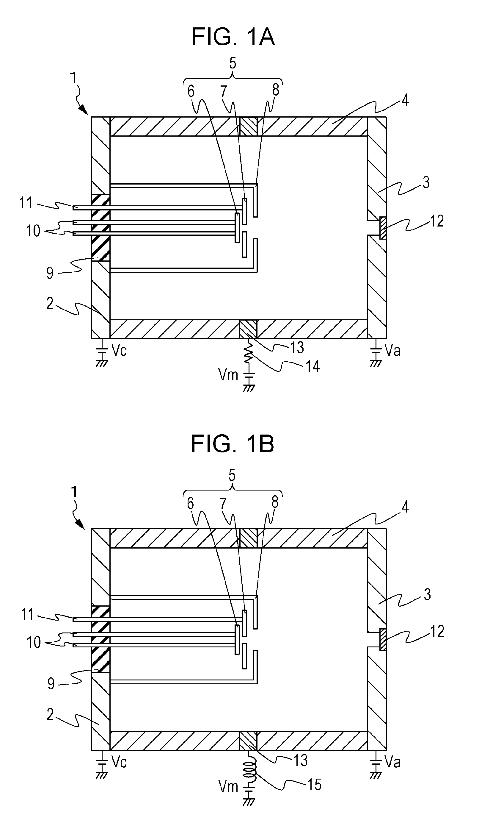
[0045]A second example differs from the first example in that an inductor 15 is provided in place of the electrical resistance member 14 as illustrated in FIG. 1B.

[0046]The same examination as that of the first example is carried out using this radiation generating tube 1 with the inductance value of the inductor 15 being set to 10 mH. A discharge current which flows into the focusing electrode 8 from the electrical potential defining member 13 is reduced in the same manner as in the first example.

[0047]Further, in the same manner as in the first example, radiation is emitted successfully by the radiation generating apparatus 17 manufactured using the radiation generating tube 1 without any disturbance of electrical discharge.

third example

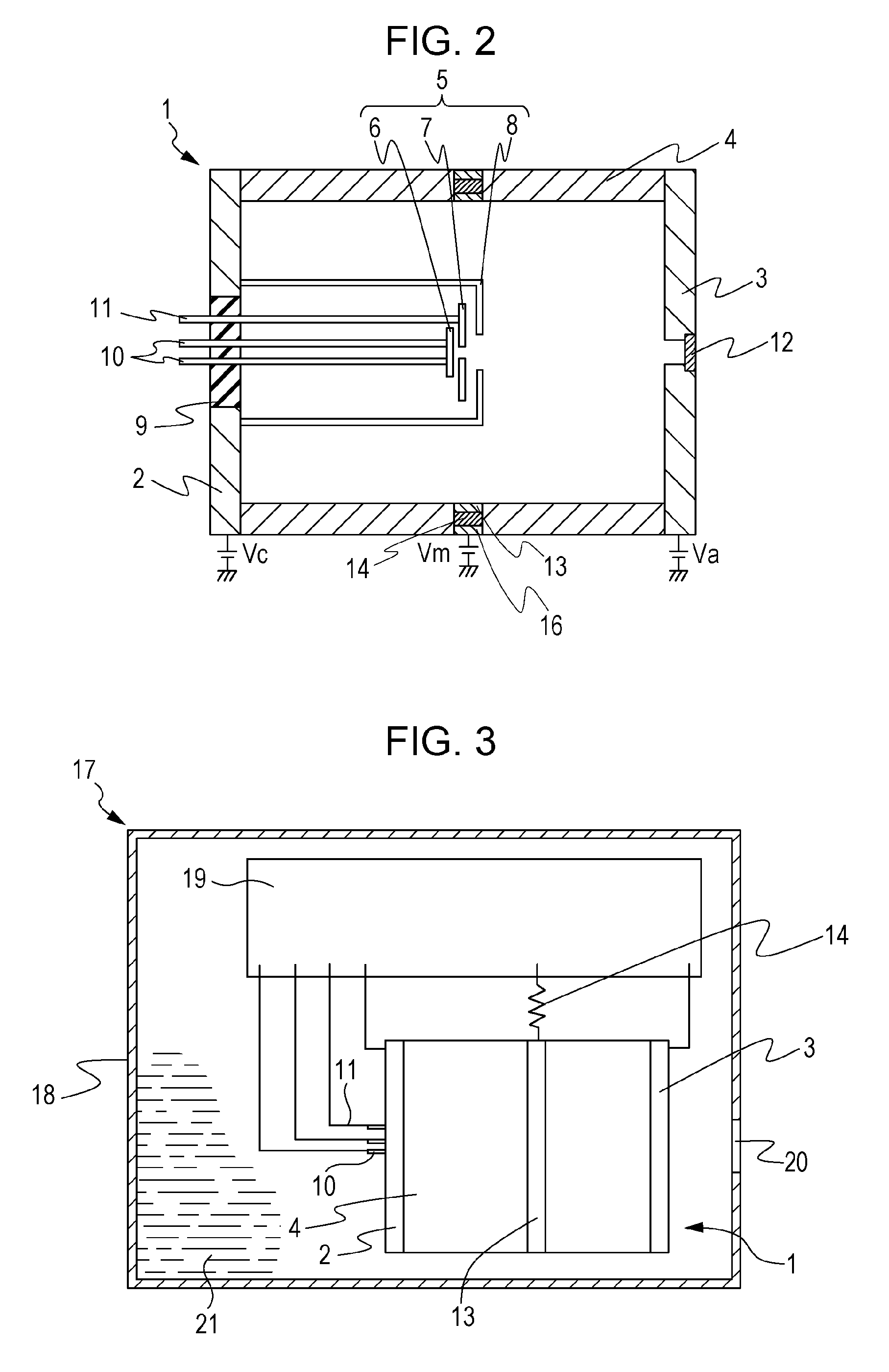
[0048]A third example differs from the first example in that, as illustrated in FIG. 2, the electrical resistance member 14 is disposed between the electrical potential defining member 13 and an electrical potential defining member 16, which is another electrical potential defining member. The electrical resistance member 14 is made of a conductive ceramic in which metallic oxide particles are dispersed. The ceramic material is machined into a ring shape. The electrical potential defining member 13 is attached to the ring-shaped ceramic material on an inner wall side of the tubular side wall 4. The electrical potential defining member 16 is attached to the ceramic material on the outer wall side of the tubular side wall 4. The thus-prepared member is formed to connect the tubular side wall 4 and the electrical potential defining member 16. The electric resistance value of the electrical resistance member 14 is set to about 1 MΩ.

[0049]In the thus-manufactured radiation generating tub...


PUM


Abstract

A radiation generating tube, which includes: a cathode connected to an electron gun structure; an anode including a target and configured to generate radiation; and a tubular side wall disposed between the cathode and the anode to surround the electron gun structure; and an electrical potential defining member disposed at an intermediate portion of the tubular side wall between the anode and the cathode. The electrical potential defining member is electrically connected to an electrical potential defining unit via an electrical resistance member or an inductor, and a potential of the electrical potential defining member is defined to be a higher potential than a potential of the cathode and to be a lower potential than a potential of the anode.

Description

BACKGROUND OF THE INVENTION[0001]1. Field of the Invention[0002]The present invention relates to a radiation generating tube which includes a transmission target. The present invention relates also to radiation generating apparatus in which the radiation generating tube is used.[0003]2. Description of the Related Art[0004]A transmission radiation generating tube is a vacuum tube including a cathode, an anode and an insulating tubular side wall. Electrons emitted from an electron source of the cathode are accelerated by high voltage applied between the cathode and the anode. The electrons collide with a transmission target on the anode and cause radiation to generate. The emitted radiation is extracted outside through a transmission target. The transmission target also functions as a radiation extraction window. Such a transmission radiation generating tube is used in radiation generating apparatus for medical and industrial use.[0005]Such a transmission radiation generating tube and...

Claims


Application Information

Patent Timeline
Patent Type & Authority Patents(United States)
IPC IPC(8): H01J35/02H01J35/16
CPCH01J35/02H01J35/16H01J2235/02H01J2235/087H01J35/116
Inventor YAMAZAKI, KOJIITO, NOBUHIROUEDA, KAZUYUKI
Owner CANON KK
Why Eureka
Try Eureka