Gasification of heavy residue with solid catalyst from slurry hydrocracking process

a technology of solid catalyst and heavy residue, which is applied in the direction of combustible gas chemical modification, combustible gas purification/modification, combustible gas production, etc., can solve the problems of high cost of design, large problems with fixed-bed technology, and commercial impracticality

Active Publication Date: 2015-06-16
SAUDI ARABIAN OIL CO
View PDF8 Cites 7 Cited by
  • Summary
  • Abstract
  • Description
  • Claims
  • Application Information

AI Technical Summary

Problems solved by technology

Fixed-bed technologies have considerable problems in treating particularly heavy charges containing high percentages of heteroatoms, metals, and asphaltenes, as these contaminants cause the rapid deactivation of the catalyst and subsequent plugging of the reactor.
Multiple fixed-bed reactors connected in series can be used to achieve a relatively high conversion of heavy feedstocks boiling above 370° C., but such design would be costly and, for certain feedstocks, commercially impractical, e.g., catalysts must be replaced every 3 to 4 months.
The fluid nature of the catalyst also allows for on-line catalyst replacement of a small portion of the bed which results in a high net bed activity.
During replacement, catalyst movement is slow compared with the linear velocity of the feed.
Disposal of the spent solid catalyst as a waste material incurs substantial expense and entails environmental considerations.
The replacement of refractory linings can cost several millions of dollars a year and several weeks of downtime for a given reactor.
Up until now, the solution has been the installation of a second or parallel gasifier to provide the necessary continuous operating capability, but the undesirable consequence of this duplication is a significant increase in the capital costs associated with the unit operation.
Both systems have demonstrated high utility with solid fuels, but not with liquid fuels.
While gasification processes are well developed and suitable for their intended purposes, its applications in conjunction with other refinery operations have been limited.

Method used


Image

  • Gasification of heavy residue with solid catalyst from slurry hydrocracking process
  • Gasification of heavy residue with solid catalyst from slurry hydrocracking process

Examples


example

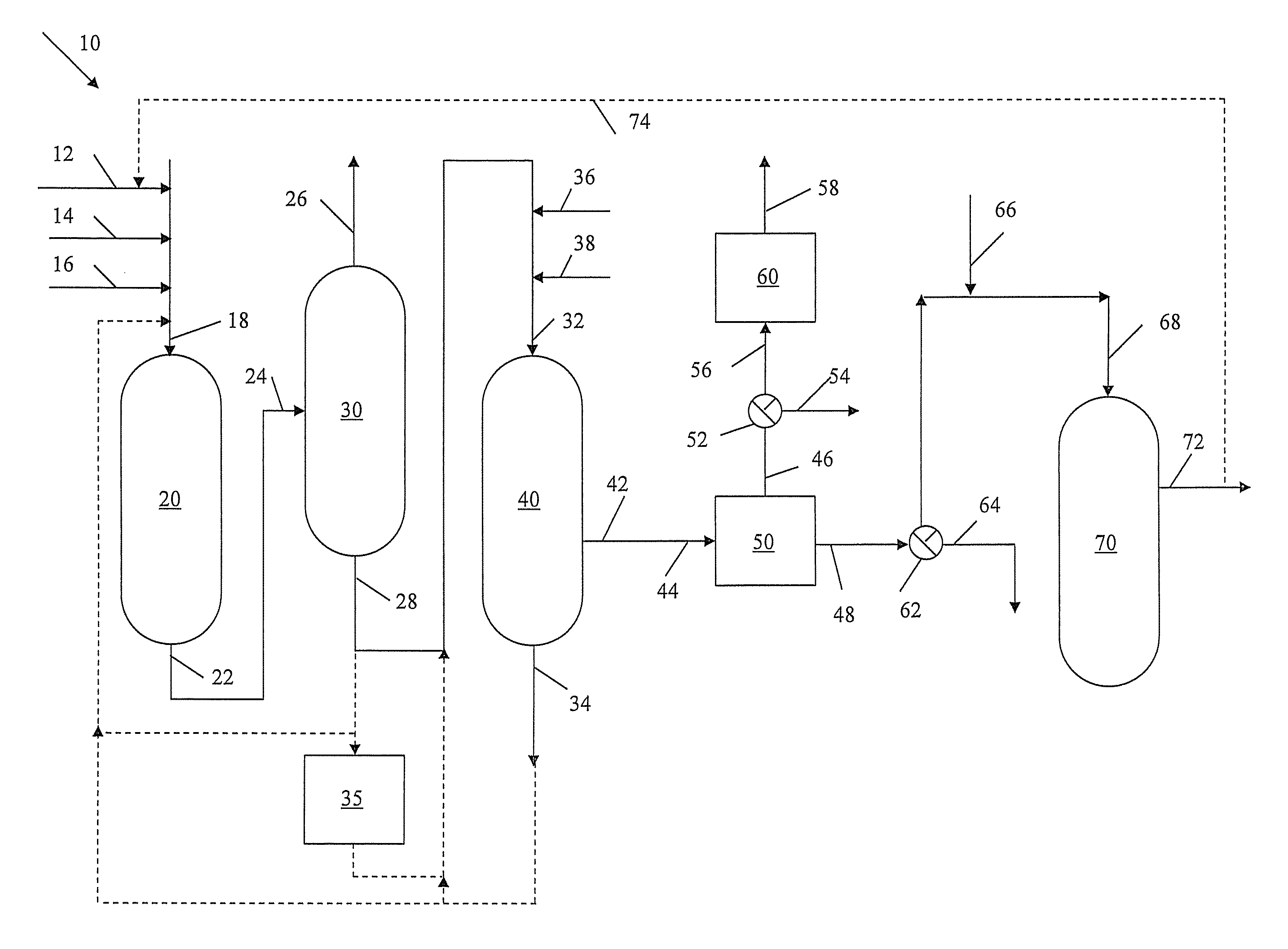
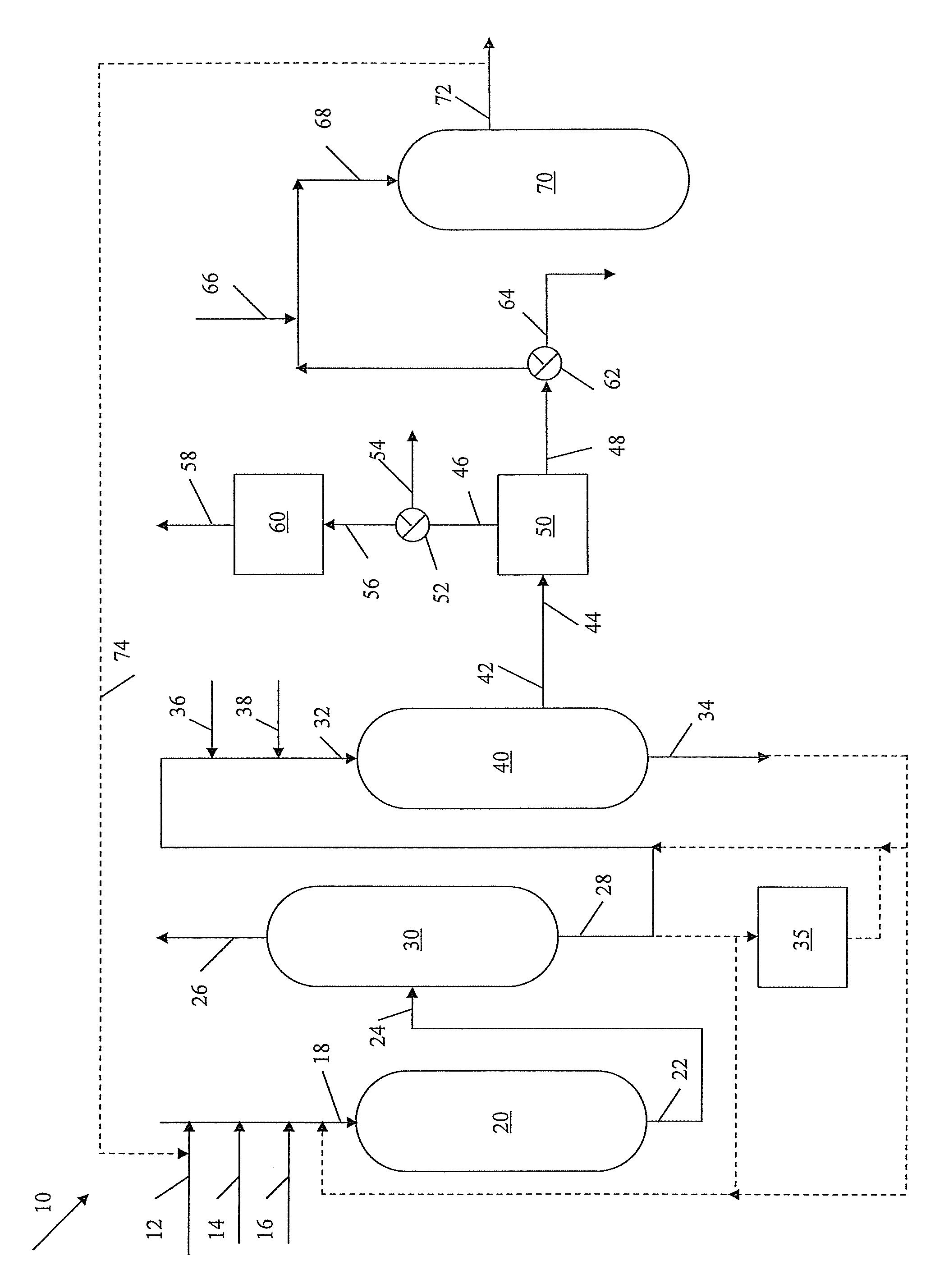
[0067]A 100 kg sample of vacuum residue boiling above 520° C. derived from Arab heavy crude oil was introduced as a pressurized feedstock into a slurry hydrocracking zone. The vacuum residue had an API gravity of 5.7 degrees and contained 5.3 W % of sulfur, 0.45 W % of nitrogen, 19.5 W % of C7-asphaltenes, 22.9 W % of CCR and 222 ppmw combined of nickel and vanadium. The slurry hydrocracking zone was operated at 420° C., 160 bars and liquid hourly space velocity of 0.5 h1. The catalyst was molybdenum sulfide on a solid support. The slurry hydrocracking conversion of vacuum residue was 85 W % and the resultant process yields are summarized in Table 1 below. The total hydrogen consumption was 1.6 W % of the feedstock processes.

[0068]

TABLE 1Slurry Hydrocracking YieldsProductBoiling PointYields W %Light GasesC1-C4 + H2S8.7NaphthaC5-170°C.0.9Gas oil170-350°C.26.2Vacuum Gas oil350-520°C.30.5Pitch>520°C.35.3Total101.6

[0069]After the separation of converted products, the heavy residue and s...


PUM

PropertyMeasurementUnit
operating temperatureaaaaaaaaaa
operating pressureaaaaaaaaaa
operating temperatureaaaaaaaaaa

Abstract

A cost-effective solution for the disposal of heavy residue bottoms recovered from a slurry hydrocracking process that include solid heterogeneous catalyst particles is provided by their introduction into a membrane wall gasification reactor in the form of a flowable slurry to produce a synthesis gas and, optionally, subjecting the synthesis gas to a water-gas shift reaction to produce a more hydrogen-rich product stream. Process steam and electricity are produced by recovering the sensible heat values from the hot synthesis gas.

Description

RELATED APPLICATIONS[0001]None.BACKGROUND OF THE INVENTION[0002]1. Field of the Invention[0003]The present invention relates to processes for the partial oxidation in a membrane wall gasification reactor of heavy residue bottoms recovered from a slurry hydrocracking process to produce a synthesis gas.[0004]2. Description of Related Art[0005]In a typical refinery, crude oil is initially introduced to an atmospheric distillation column or a crude tower where it is separated into a variety of different components including naphtha boiling in the range 36° C. to 180° C., diesel boiling in the range 180° C. to 370° C., and atmospheric bottoms boiling above 370° C. The atmospheric bottoms residue is further processed in a vacuum distillation column where it is separated into a vacuum gas oil (VGO) boiling in the range 370° C. to 520° C. and a heavy vacuum residue boiling above 520° C. The VGO may be further processed by hydrocracking to produce naphtha and diesel, or by fluid catalytic cr...

Claims


Application Information

Patent Timeline
Patent Type & Authority Patents(United States)
IPC IPC(8): C10G67/12C10G47/26C10G47/06C10G65/14C01B3/36C10G47/14C10G47/00C10G65/00
CPCC01B3/36C10G65/14C10G67/12C10G47/26C10G47/06C10G47/14C01B2203/0255C01B2203/0283C01B2203/063Y02E20/18Y02P20/145C10G47/10C10J3/466C10J3/82C10J2300/0946C10J2300/0959C10J2300/0976C10J2300/1675C10J2300/1846F01K23/067
Inventor KOSEOGLU, OMER REFABALLAGUET, JEAN-PIERRE
Owner SAUDI ARABIAN OIL CO
Why Eureka
Try Eureka