Supercharge Your Innovation With Domain-Expert AI Agents!

Method for detecting and locating fluid ingress in a wellbore

a wellbore and fluid detection technology, applied in seismology, geological measurement, survey, etc., can solve the problems of not generating revenue, path of such fluids to the surface, and serious environmental concerns, and achieve the effect of easy analysis of signals

Active Publication Date: 2015-06-16
HIFI ENG
View PDF13 Cites 1 Cited by
  • Summary
  • Abstract
  • Description
  • Claims
  • Application Information

AI Technical Summary

Benefits of technology

This approach significantly improves the accuracy of fluid ingress location detection, reducing costly misdiagnoses and enabling more effective sealing of leaks, thereby enhancing operational efficiency and reducing expenses.

Problems solved by technology

As explained in WO 2008 / 098380 assigned to a common owner of the within application, ingress of fluids such as gases or liquids into wellbores, where such fluids may (and typically do) then migrate to surface in the area between the wellbore and the casing and thus undesirably escape into the atmosphere, are a serious and increasing environmental concern.
Specifically, fluids which seep into wellbores commonly comprise gases and liquids which are toxic, such as for example and including hydrogen sulfide, and / or are greenhouse gases such as methane.
The path of such fluids to the surface can arise due to fractures around the wellbore, fractures in the production tubing, poor casing to cement / cement-to-formation bond, channeling in the cement, or various other reasons.
The repair of these situations does not generate revenue for the gas / oil company, and can cost millions of dollars per well to fix the problem.
It is known, and existing systems for leak detection rely on the fact, that ingress of fluids into a wellbore typically generates a noise (acoustic signal), such as a “hiss” from high pressurized gas seeping into the wellbore, or from fluid intermittently “bubbling” into a wellbore.
These prior art techniques only work well for high rate leaks (i.e., where the ingress of fluid into the wellbore is high and generating significant and high power acoustic signal from a pinpoint location in the well bore), and where there is relatively low background noise or little interference from other noise sources such as surface noise, and reverberation and resulting sound amplification at other locations in the well is not occurring or is not significant.
Using comparisons of the power or strength of the various acoustic signals in such manner as done in the prior art is highly unsatisfactory, as reverberations in wellbores frequently produces higher noise levels at locations within the wellbore considerable remote from the location in the wellbore which is the actual source of the acoustic event, and are thus unsatisfactory for attempting to precisely locate the location of fluid ingress in a wellbore.
As well, where fluid ingress into the wellbore is not under high pressure (but may be still significant in terms of amount) and thus the corresponding acoustic signal is substantially reduced in magnitude and / or is of a sporadic nature such as when gases or liquids bubble periodically into the wellbore, the ability to identify which acoustic signal (and thus the location in the wellbore) that is experiencing fluid ingress is considerably more difficult under the aforementioned prior art methods, and is very unreliable.
Again, factors such as reverberation and echoes (as nearly always occur with acoustic signals in wellbores) and / or interfering surface noise each have the undesirable consequence of often making acoustic signals remote from the location of the acoustic event stronger and possessing more power than the acoustic signal emanating from a location in the wellbore most proximate the acoustic event.
As a result, various (incorrect) locations in such wellbore were, through laborious effort and expense, injected with cement in an attempt to “seal” the wellbore at such locations from CVM and fluid ingress, but which efforts were not successful due to prior art methods being unable to satisfactorily analyze the acoustic signals to as to be able to accurately identify the location the wellbore fluid ingress was occurring.
For example, simply conducting an amplitude versus time analysis of acoustic signals received at various locations along the wellbore may not be sufficient to permit easy identification of a common component within such signals, namely a common component having a phase angle which is progressively delayed in acoustic signals obtained from proximate locations in a wellbore.

Method used


Image

  • Method for detecting and locating fluid ingress in a wellbore
  • Method for detecting and locating fluid ingress in a wellbore
  • Method for detecting and locating fluid ingress in a wellbore

Examples


example 1

[0112]A simulated wellbore having a source of fluid ingress was created. Specifically, vertical sections of 4½ inch (outside diameter) lengths of ¼ inch steel pipe were co-axially placed within vertical sections of 6 inch (outside diameter) lengths of steel pipe, and the respective sections welded together to form a simulated wellbore of 43 m in length, having an inner annulus between the pipe diameters of approximately 1 inch simulating a distance between a casing in a wellbore, and an exterior of the wellbore.

[0113]Fluid (water) at approximately 20° C. was bubbled into the above annulus via a 1 / 16 inch aperture in the exterior 6 inch pipe, at a rate of approximately 5 ml per minute, at a location 25 m along a vertical length of such pipe (measured from the base when such simulated wellbore was in the vertical position-hereinafter all dimensions from the base of such structure).

[0114]A simulated obstruction was placed in the formed annulus, at a location of 15 m along the vertical ...

example 2

[0128]The aforementioned steps of Example 1 were repeated with the fibre optic cable in the simulated wellbore being lowered to a position below the location of fluid ingress at 25 m, namely to a position wherein acoustic signals could be obtained from positions of 38 m and 40 m respectively from the top of the wellbore, and accordingly 13 m and 15 m respectively below the source of fluid ingress at 25 m.

[0129]An acoustic signal having a plurality of significant amplitudes separated by periods of little acoustic significance were obtained from each of the aforementioned positions in the wellbore. It was considered that the above type of acoustic signal corresponded to and was representative of intermittent bubbling of fluid into the well.

[0130]A bandpass filter was used so as to pass acoustic signals with a frequency in the specific low frequency range of 200 Hz partial filtering of the acoustic signals to only low the low frequency range was desirable in view of the fact fluid ingr...

example 3

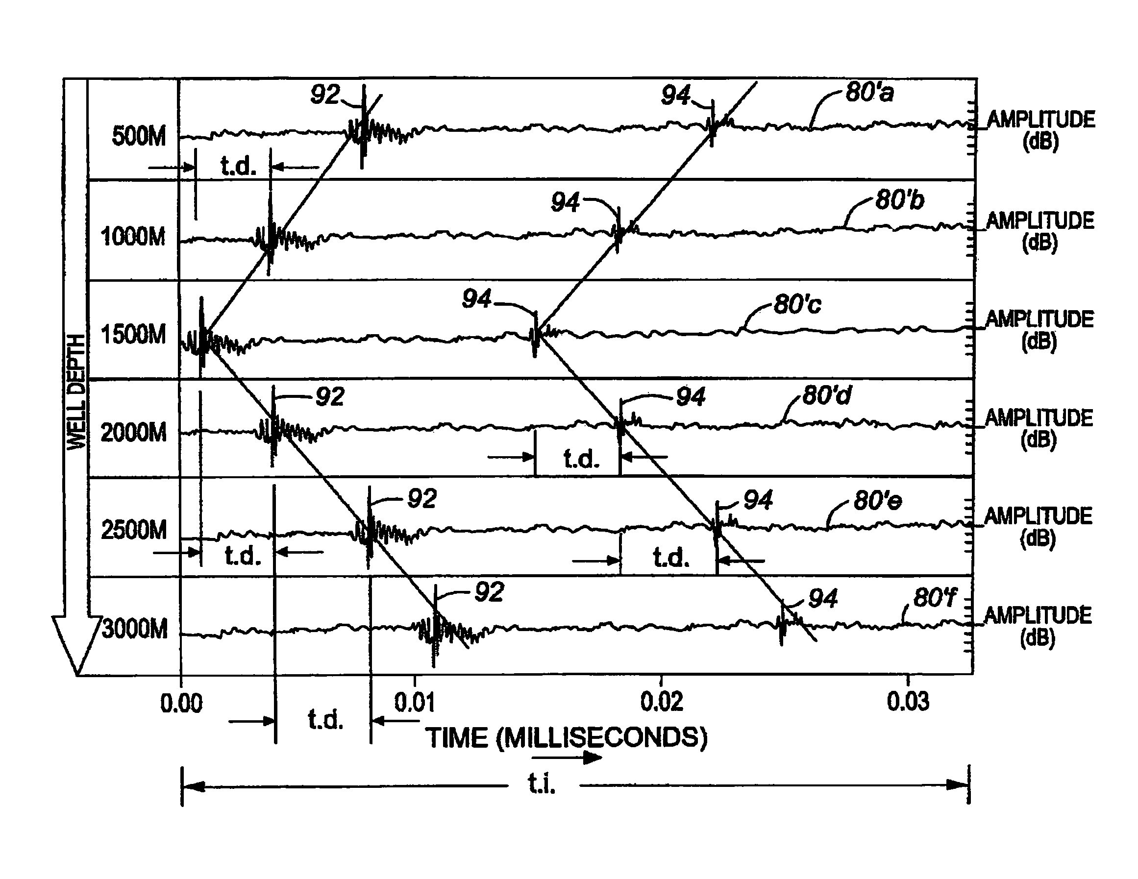
[0133]The acoustic signals of Example 2 were examined, at a different time, namely at a point in time having another single significant event from each of the two acoustic signals from each of the two locations, over a period of approximately 30 milliseconds (i.e., 4.220-4.250 seconds) which was selected as the time interval.

[0134]FIG. 13 graphically represents the aforesaid signals over time, with channel 1 (ch. 1) being the acoustic signal received from the 38 m location along the simulated wellbore and being the location closest (i.e., 13 m) from the location of fluid ingress at 25 m as measured from the top of the pipe, with channel 2 (ch. 2) being the acoustic signal received from the 40 m location along the simulated wellbore and being the location the farthest (i.e., 15 m) of the two to the location of fluid ingress at 25 m.

[0135]As may be seen from FIG. 13, acoustic signal on ch. 1 being located 13 m from the source of fluid ingress in the simulated wellbore, provided the si...


PUM


Abstract

A method for detecting fluid ingress in a wellbore. An acoustic sensor is placed along a wellbore. The acoustic sensor is adapted to sense individual acoustic signals from a plurality of corresponding locations along the wellbore. The individual acoustic signals are analyzed to determine if there exists a common acoustic component in acoustic signals generated from proximate locations in the wellbore. If so, the acoustic signal having the common acoustic component which appears earliest in phase, by virtue of such acoustic signal's corresponding location in the wellbore, determines the location in the wellbore of likely fluid ingress. The acoustic sensor may be a fiber optic cable extending substantially the length of the wellbore, or alternatively a plurality of microphones situated at various locations along the wellbore.

Description

CROSS-REFERENCE TO RELATED APPLICATIONS[0001]Priority is claimed from Canadian patent application 2,691,462 filed Feb. 1, 2010, entitled, “Method For Detecting And Locating Fluid Ingress In A Wellbore,” listing John Hull as inventor, such Canadian patent application incorporated herein by reference.FIELD[0002]The present invention relates to fluid migration in oil or gas wells, and more particularly to a method of detecting ingress of fluid along a wellbore.BACKGROUND[0003]This section provides background information related to the present disclosure which is not necessarily prior art.[0004]As explained in WO 2008 / 098380 assigned to a common owner of the within application, ingress of fluids such as gases or liquids into wellbores, where such fluids may (and typically do) then migrate to surface in the area between the wellbore and the casing and thus undesirably escape into the atmosphere, are a serious and increasing environmental concern. Specifically, fluids which seep into well...

Claims


Application Information

Patent Timeline
Patent Type & Authority Patents(United States)
IPC IPC(8): E21B47/10
CPCE21B47/101E21B47/107
Inventor HULL, JOHN
Owner HIFI ENG
Features
  • R&D
  • Intellectual Property
  • Life Sciences
  • Materials
  • Tech Scout
  • Unparalleled Data Quality
  • Higher Quality Content
  • 60% Fewer Hallucinations
Learn More