Radiation irradiation device, radiation irradiation method and program storage medium

a radiation irradiation and program storage technology, applied in the field of radiation irradiation devices, radiation irradiation methods and program storage media, can solve the problems of large radiation source output, limited radiation source output, and limited radiation source cross-section profile, so as to reduce damage to normal cells and high therapeutic

Inactive Publication Date: 2015-07-14
FUJIFILM CORP
View PDF23 Cites 12 Cited by
  • Summary
  • Abstract
  • Description
  • Claims
  • Application Information

AI Technical Summary

Benefits of technology

[0059]The aspects described above enable generation of radiation beams for MRT without requiring a large-scale facility.
[0060]Moreover, the aspects described above enable irradiation of radiation beams with high therapeutic effect over a wide range, while reducing damage to normal cells.

Problems solved by technology

In order to implement the technology described in the above documents, a large-scale synchrotron radiation facility is required to generate synchrotron radiation, thereby limiting locations where the technology can be implemented.
Patients of cancer, which is the biggest cause of death in Japan, face the inconvenience of having to go to a large-scale synchrotron radiation facility in order to receive MRT using this technology.
As a result, a very large radiation source output is required in order to obtain radiation doses used for treatment, which gives rise to many issues in configuring a device such that heat generation and shielding.
Further, while the MRT technology described in the above documents enables destroying cancer cells while hardly destroying any normal cells as described above, the size of a cross-section profile of the radiation beam that can be generated, in an orthogonal direction to the direction of travel of the radiation beam, is limited.
Therefore, the size of a tumor may be wider in range than the cross-section profile in a case of performing MRT radiation treatment, and in such case radiation treatment of the whole tumor cannot be performed.

Method used


Image

  • Radiation irradiation device, radiation irradiation method and program storage medium
  • Radiation irradiation device, radiation irradiation method and program storage medium
  • Radiation irradiation device, radiation irradiation method and program storage medium

Examples


first exemplary embodiment

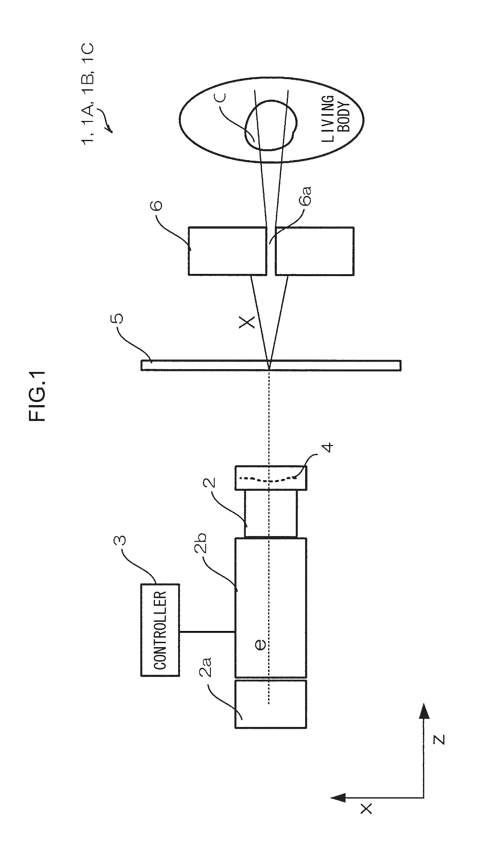
[0113]Detailed explanation follows regarding a radiation (X-ray) irradiation device according to a first exemplary embodiment, with reference to the appended drawings.

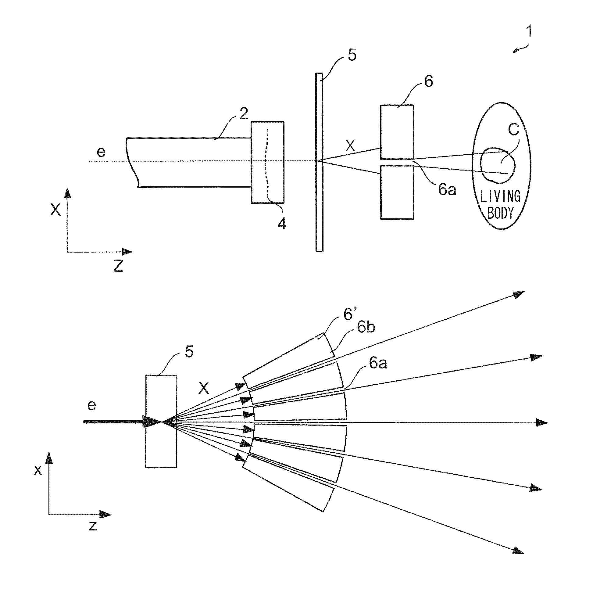
[0114]FIG. 1 is a plan view illustrating an overall configuration of a radiation irradiation device 1 according to the first exemplary embodiment.

[0115]As illustrated in FIG. 1, the radiation irradiation device 1 includes an electron gun 2a that generates an electron beam e, a low emittance accelerator 2b that accelerates the generated electron beam e while lowering the emittance, and a beam duct 2 that guides the accelerated low emittance electron beam (also referred to below simply as electron beam e) to outside. The radiation irradiation device 1 also includes a controller 3, which performs control of operations such as generation of the electron beam e by the electron gun 2a, measurement of beam current, beam speed and beam diameter of the electron beam e accelerated by the low emittance accelerator 2b, and magneti...

second exemplary embodiment

[0137]Detailed explanation follows regarding operation of a radiation irradiation device 1A according to a second exemplary embodiment, with reference to the appended drawings. The radiation irradiation device 1A according to the second exemplary embodiment is configured by providing deflection magnets 7 at the periphery of the beam duct 2 of the radiation irradiation device 1 according to the first exemplary embodiment. Note that the same reference numerals are allocated to the same configurations as those of the first exemplary embodiment, and duplicate explanation thereof is omitted.

[0138]FIG. 7A is a schematic plan view illustrating relevant portions of the radiation irradiation device 1A according to the second exemplary embodiment, and FIG. 7B is a schematic side view thereof. As illustrated in FIG. 7A and FIG. 7B, the radiation irradiation device 1A according to the second exemplary embodiment has the deflection magnets 7 provided at the periphery of the beam duct 2.

[0139]FIG...

third exemplary embodiment

[0145]Detailed explanation follows regarding a radiation irradiation device 1B according to a third exemplary embodiment, with reference to the appended drawings. The radiation irradiation device 1B according to the third exemplary embodiment is configured by providing an alternating current magnet 8 in place of the deflection magnets 7 at the periphery of the beam duct 2 of the radiation irradiation device 1A according to the second exemplary embodiment. The same reference numerals are allocated to the same configurations as those of the first exemplary embodiment and the second exemplary embodiment, and duplicate explanation thereof is omitted.

[0146]FIG. 11A is a schematic plan view illustrating relevant portions of the radiation irradiation device 1B according to a third exemplary embodiment, and FIG. 11B is a schematic side view thereof. As illustrated in FIG. 11A and FIG. 11B, in the radiation irradiation device 1B according to the third exemplary embodiment, the alternating cu...


PUM


Abstract

A radiation irradiation device is provided that includes: a metal target that emits bremsstrahlung X-rays as a radiation beam due to irradiation with an electron beam; a radiation shielding member that includes a slit-shaped radiation passage portion and that is disposed downstream of the metal target in the radiation beam emission direction and is disposed such that a portion of the radiation beam passes through the radiation passage portion and the radiation beam incident to regions other than the radiation passage portion is blocked; and an electron beam generating device that irradiates, onto the metal target, an electron beam such that a diameter at a generation point of the emitted radiation beam is smaller than a length of an entry portion of the radiation passage portion along a length direction of the entry portion.

Description

CROSS-REFERENCE TO RELATED APPLICATIONS[0001]This application is a continuation application of International Application No. PCT / JP / 2012 / 078244, filed Oct. 31, 2012, the disclosure of which is incorporated herein by reference in its entirety. Further, this application claims priority from Japanese Patent Application No. 2011-241520, filed on Nov. 2, 2011, and Japanese Patent Application No. 2011-289468, filed on Dec. 28, 2011, the disclosures of which are incorporated by reference herein in their entirety.BACKGROUND OF THE INVENTION[0002]1. Field of the Invention[0003]The present invention relates to a radiation irradiation device that irradiates radiation, a radiation irradiation method of the radiation irradiation device, and a program storage medium.[0004]2. Related Art[0005]As a medical treatment method using radiation, Japanese Patent Application Laid-Open (JP-A) No. 2010-68908 discloses a particle beam treatment device that uses a multileaf collimator, in which the shape of le...

Claims


Application Information

Patent Timeline
Patent Type & Authority Patents(United States)
IPC IPC(8): A61N5/10G21K1/02H01J35/00H05G2/00H01J35/12H01J35/16
CPCA61N5/1077G21K1/02H01J35/00H01J35/12H01J35/16H05G2/00A61N2005/1095A61N2005/1094
Inventor AGANO, TOSHITAKAKUWABARA, TAKAOSHIMIZU, HITOSHI
Owner FUJIFILM CORP
Why Eureka
Try Eureka