Light scanning apparatus

a scanning apparatus and light technology, applied in the direction of electrographic process apparatus, mounting, instruments, etc., can solve the problems of non-uniform temperature distribution, low thermal conductivity coefficient of resin optical boxes, and inability to meet the needs of the user, so as to reduce the deformation of optical boxes and simple configuration

Inactive Publication Date: 2015-07-21
CANON KK
View PDF10 Cites 25 Cited by
  • Summary
  • Abstract
  • Description
  • Claims
  • Application Information

AI Technical Summary

Benefits of technology

[0009]The present invention has been achieved under the above-mentioned circumstances, and it is an object of the present invention to reduce the deformation of an optical box with a simple configuration.

Problems solved by technology

In particular, the use of an optical box made of a resin is greatly advantageous in a tandem type image forming apparatus, because a large number of optical components are used, and further mounting directions and mounting methods of supporting and fixing the optical components are not uniform.
Further, the optical box made of a resin has a low coefficient of thermal conductivity, compared to the optical box made of a metal.
Therefore, when the optical box made of a resin is used, in the light scanning apparatus containing a heat source, a temperature distribution becomes non-uniform, and a hot portion and a cold portion occur partially.
As a result, warpage and local distortion in different directions occur in the optical box.
Therefore, the optical box is greatly distorted and deformed by a non-uniform increase in temperature in the light scanning apparatus.
Consequently, the optical box increases in temperature locally, which causes the deformation such as warpage and distortion in the optical box.
Further, the IC chip mounted on the motor portion also generates heat.
Then, portions immediately below the rotation shaft receiving portion and the location where the IC chip is mounted are heated locally by the radiation heat, with the result that the optical box expands and deforms.
As described above, by the deformation of the optical box, directions and amounts of light beams vary in different color stations so that light-condensing positions on surfaces to be scanned are changed, and thus a horizontal direction, a vertical direction, or a magnification of an image line is fluctuated, resulting in the degradation in image.
In particular, in a tandem type image forming apparatus, a light beam position of each color is fluctuated, and hence color misregistration occurs when toner images of respective colors are superimposed.
However, according to the conventional method, certain effects are obtained with respect to the first cause of the deformation of the optical box described above, but there is a risk in that effects may not be obtained with respect to the second cause.
That is, hot current of air generated from the deflector can be diffused to the periphery; however, hot current of air is blown to the inclined portion of the optical box, with the result that the entire optical box is greatly distorted by the distortion caused by the expansion and deformation of the inclined portion.
Further, the local deformation of the rotation shaft receiving portion of the rotary polygon mirror and also the deformation of expansion from the center of the rotation shaft receiving portion to the periphery thereof cannot be absorbed by the inclined portion formed into a straight line shape, which leads to the deformation of the entire optical box.

Method used


Image

  • Light scanning apparatus
  • Light scanning apparatus
  • Light scanning apparatus

Examples


first embodiment

Configuration of Image Forming Apparatus

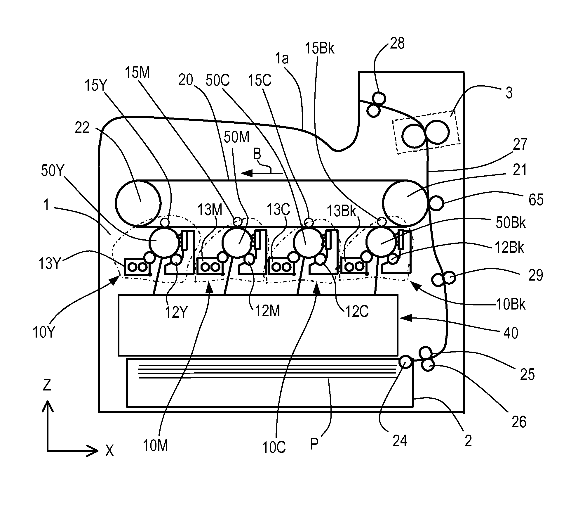
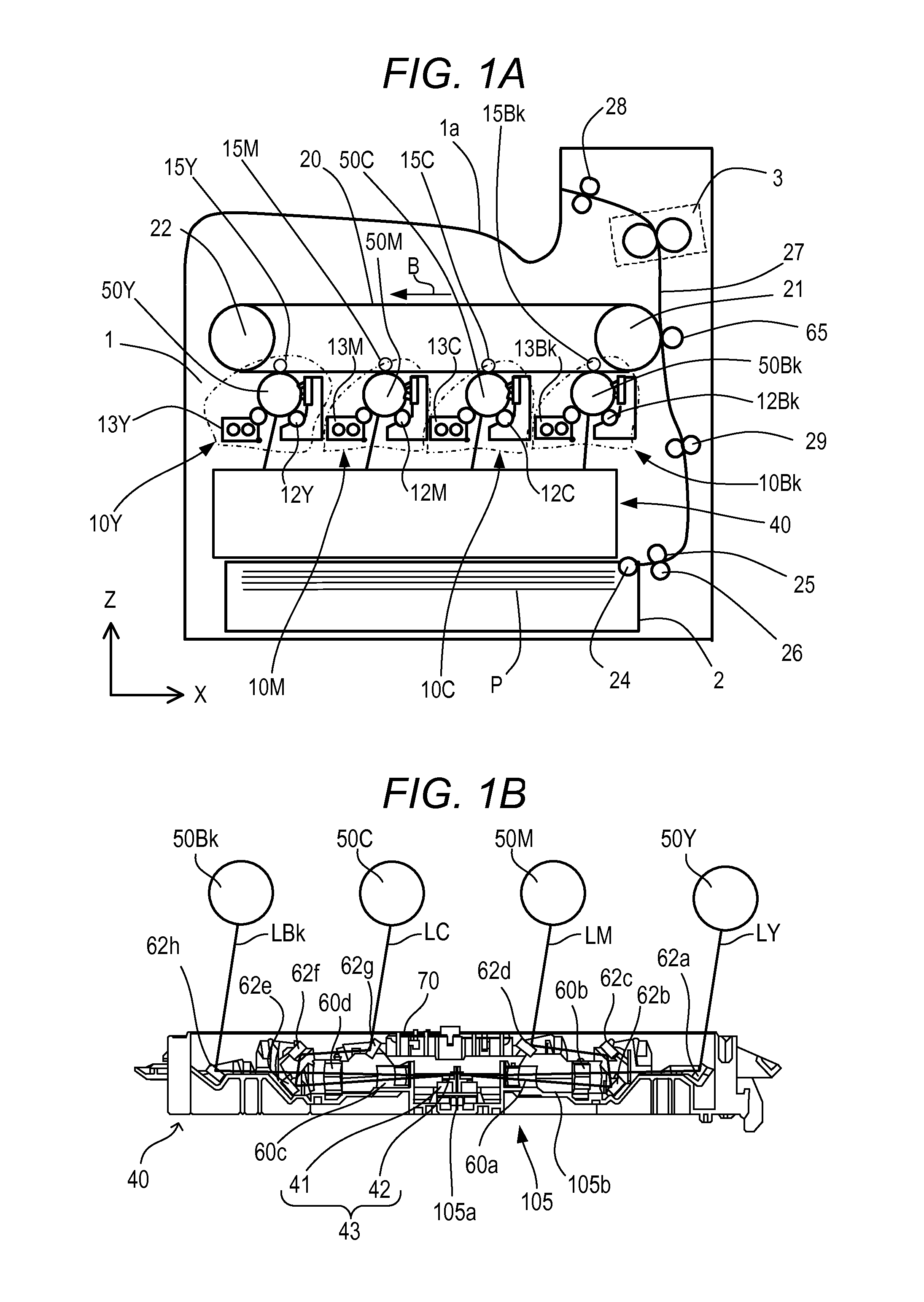
[0025]The configuration of an image forming apparatus according to a first embodiment will be described. FIG. 1A is a schematic structural view illustrating an entire configuration of a tandem type color laser beam printer of the embodiment. The laser beam printer (hereinafter referred to simply as “printer”) includes four image forming engines (image forming portions) 10Y, 10M, 10C, and 10Bk (indicated by dashed-dotted lines) configured to form toner images of respective colors: yellow (Y), magenta (M), cyan (C), and black (Bk). Further, the printer includes an intermediate transfer belt 20 onto which a toner image is transferred from each of the image forming engines 10Y, 10M, 10C, 10Bk. Then, the printer is configured in such a manner that the toner images multi-transferred onto the intermediate transfer belt 20 are transferred onto a recording sheet P serving as a recording medium to form a full-color image.

[0026]The intermediate transfer ...

second embodiment

Configuration of Stepped Portion

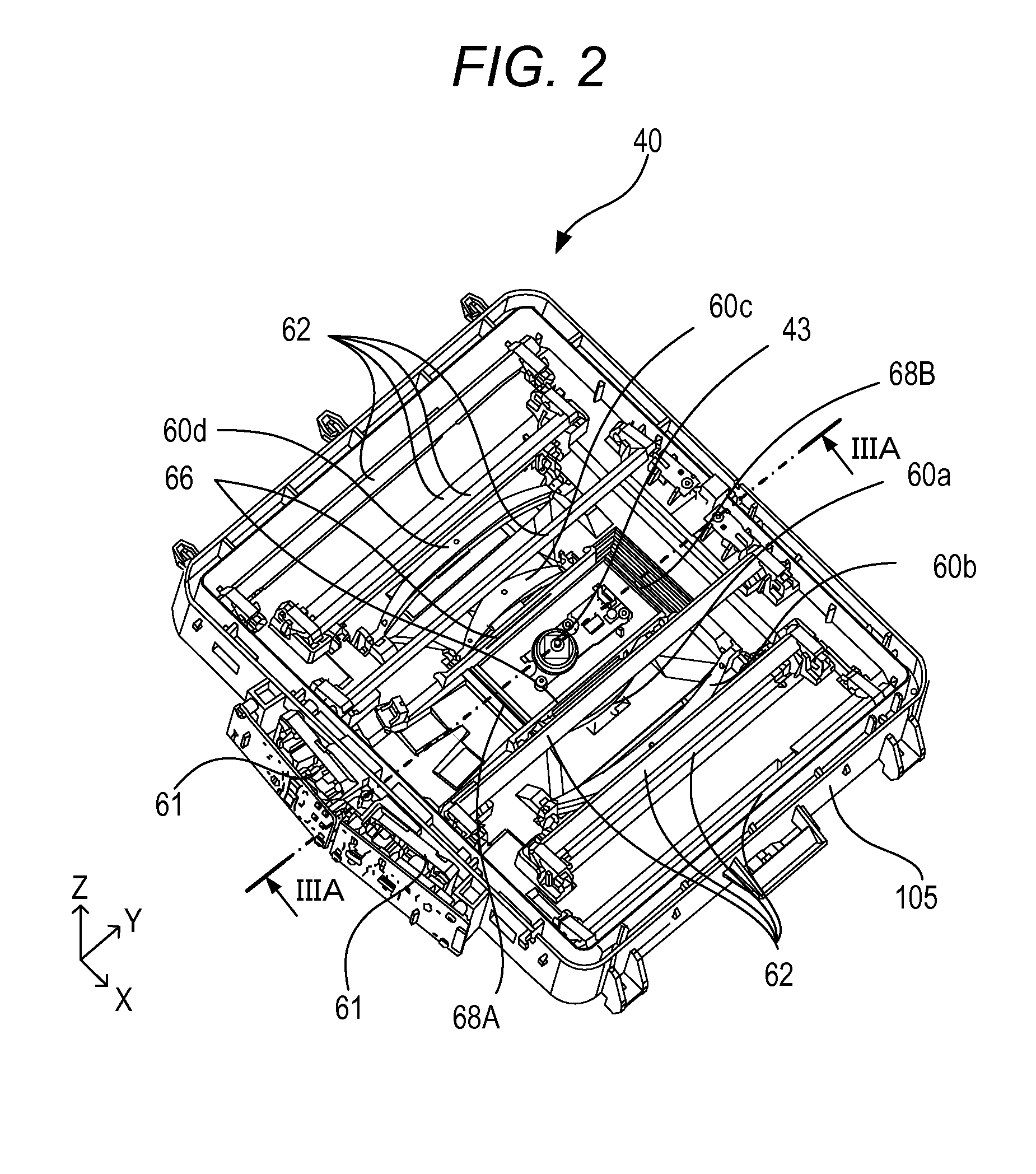
[0070]FIG. 7 is a view illustrating the configuration of a stepped portion 168 of a second embodiment. A stepped portion 168A and a stepped portion 168B of the embodiment are configured so that the thickness of each wall forming the stepped portions 168A and 168B is non-uniform. In the embodiment, in the stepped portion 168B, a thickness of portions 168B1 perpendicular to the bottom wall 105a of the optical box 105 is thinner than a thickness of portions 168B2 parallel to the bottom wall 105a of the optical box 105. Note that, the portion 168B1 corresponds to the first wall 68B1 of the first embodiment, and the portion 168B2 corresponds to the second wall 68B2 of the first embodiment. Similarly, in the stepped portion 168A, a thickness of first walls 168A1 corresponding to the first wall 68A1 of the first embodiment is thinner than a thickness of second walls 168A2 corresponding to the second wall 68A2 of the first embodiment. With such a configuratio...


PUM


Abstract

A light scanning apparatus, including: a light source; a deflector having a rotary polygon mirror configured to deflect the light beam emitted from the light source, and a motor configured to rotate the polygon mirror; a plurality of reflecting mirrors configured to reflect the light beam to the photosensitive member; and an optical box on which the light source is mounted, wherein the optical box has an installation wall on which the deflector is installed and a support wall positioned on a side of the photosensitive member with respect to the polygon mirror, the support wall being provided with a support portion configured to support at least one reflecting mirror, a stepped portion having a plurality of steps is formed between the installation wall and the support wall, and a back surface of the stepped portion has a shape following an inside surface of the stepped portion.

Description

BACKGROUND OF THE INVENTION[0001]1. Field of the Invention[0002]The present invention relates to a light scanning apparatus used in an image forming apparatus such as a copying machine, a printer, a facsimile machine, and a multifunctional peripheral thereof.[0003]2. Description of the Related Art[0004]As a light scanning apparatus used in an electrophotographic image forming apparatus, a light scanning apparatus having the following configuration is well known. Specifically, there has been known a light scanning apparatus configured to deflect a light beam emitted from a light source by a rotary polygon mirror and to guide the deflected light beam onto a photosensitive surface of the photosensitive member by optical components such as a lens and a mirror, to form a latent image on a photosensitive member. An imaging optical system is formed of at least one fθ lens. The fθ lens has a special lens effective surface typified by an aspheric surface for the purpose of enhancing scanning...

Claims


Application Information

Patent Timeline
Patent Type & Authority Patents(United States)
IPC IPC(8): B41J2/385G03G15/043
CPCG03G15/0435G03G2215/0132G02B7/181G02B26/121G02B26/125
Inventor OTOGURO, YASUAKIISHIDATE, TAKEHIRO
Owner CANON KK
Why Eureka
Try Eureka