
Construction machine

a construction machine and construction technology, applied in the direction of electric control, speed sensing governor, engine starter, etc., can solve the problems of easy air bubbles and cavitation, follow unsolved problems, and reduce the durability and life of hydraulic equipmen

Active Publication Date: 2015-07-28
NIHON KENKI CO LTD
View PDF4 Cites 2 Cited by
  • Summary
  • Abstract
  • Description
  • Claims
  • Application Information

AI Technical Summary

Benefits of technology

The invention tries to solve the problem of a hydraulic pump sucking cold hydraulic oil from its tank, which causes negative pressure and results in air bubbles and cavitation, reducing the durability and lifespan of hydraulic equipment, especially in the case of a construction machine where the engine is directly connected to the hydraulic pump. The invention proposes a solution to prevent these issues and improve the performance of the engine in low-temperature environments.

Problems solved by technology

However, there are also following unsolved problems.
As a result, the hydraulic oil sucked into the hydraulic pump from an hydraulic oil tank tends to have a negative pressure, which makes air bubbles and cavitation easily occur and causes reduction in durability and a life of hydraulic equipment.
Thus, in case the engine is started at a low temperature while the dial of the rotational speed setting device is operated to the high idling side, an engine rotational speed rapidly rises to the high idling rotational speed, and it causes a problem that air bubbles and cavitation easily occur in the hydraulic oil.

Method used


Image

  • Construction machine
  • Construction machine
  • Construction machine

Examples


first embodiment

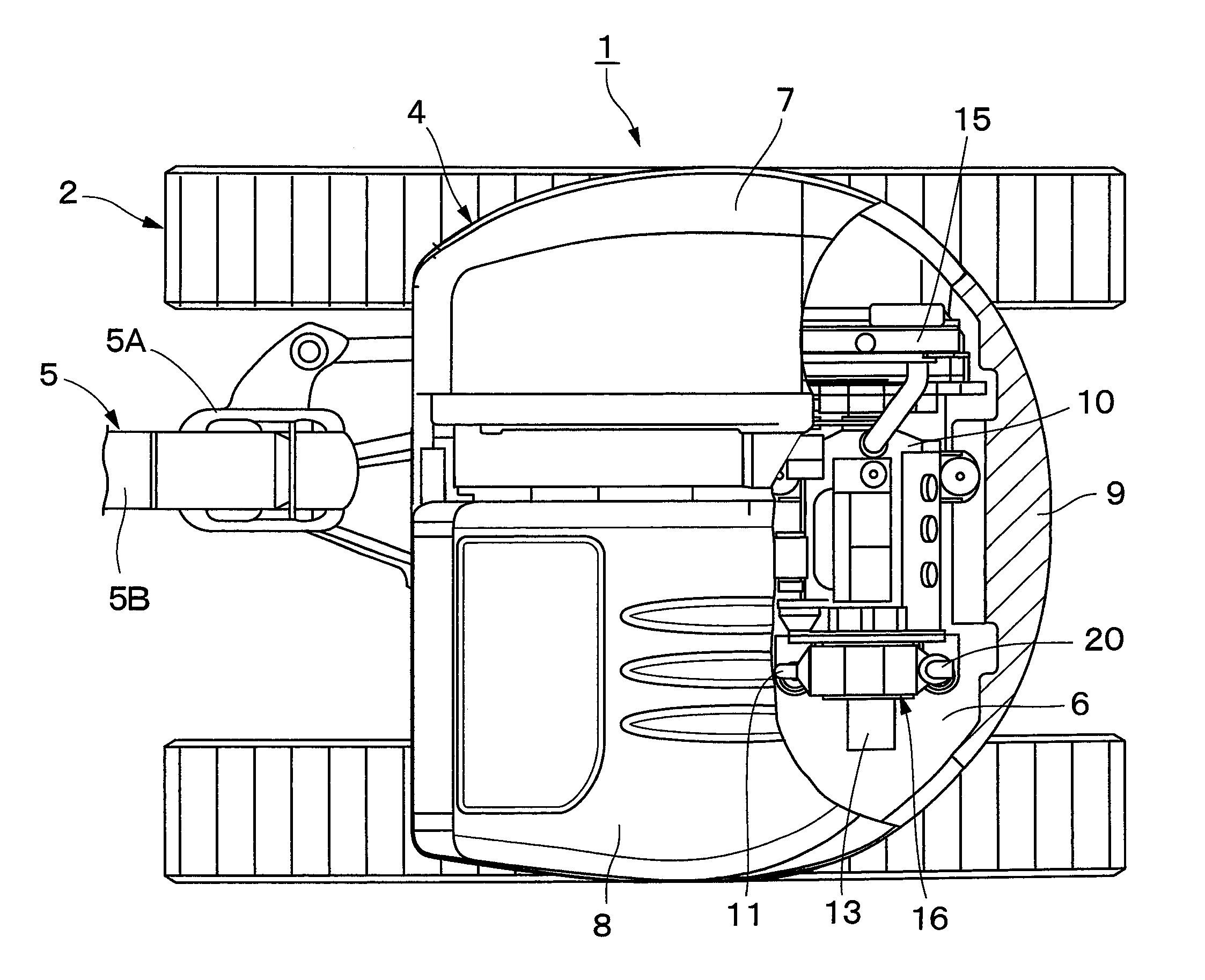
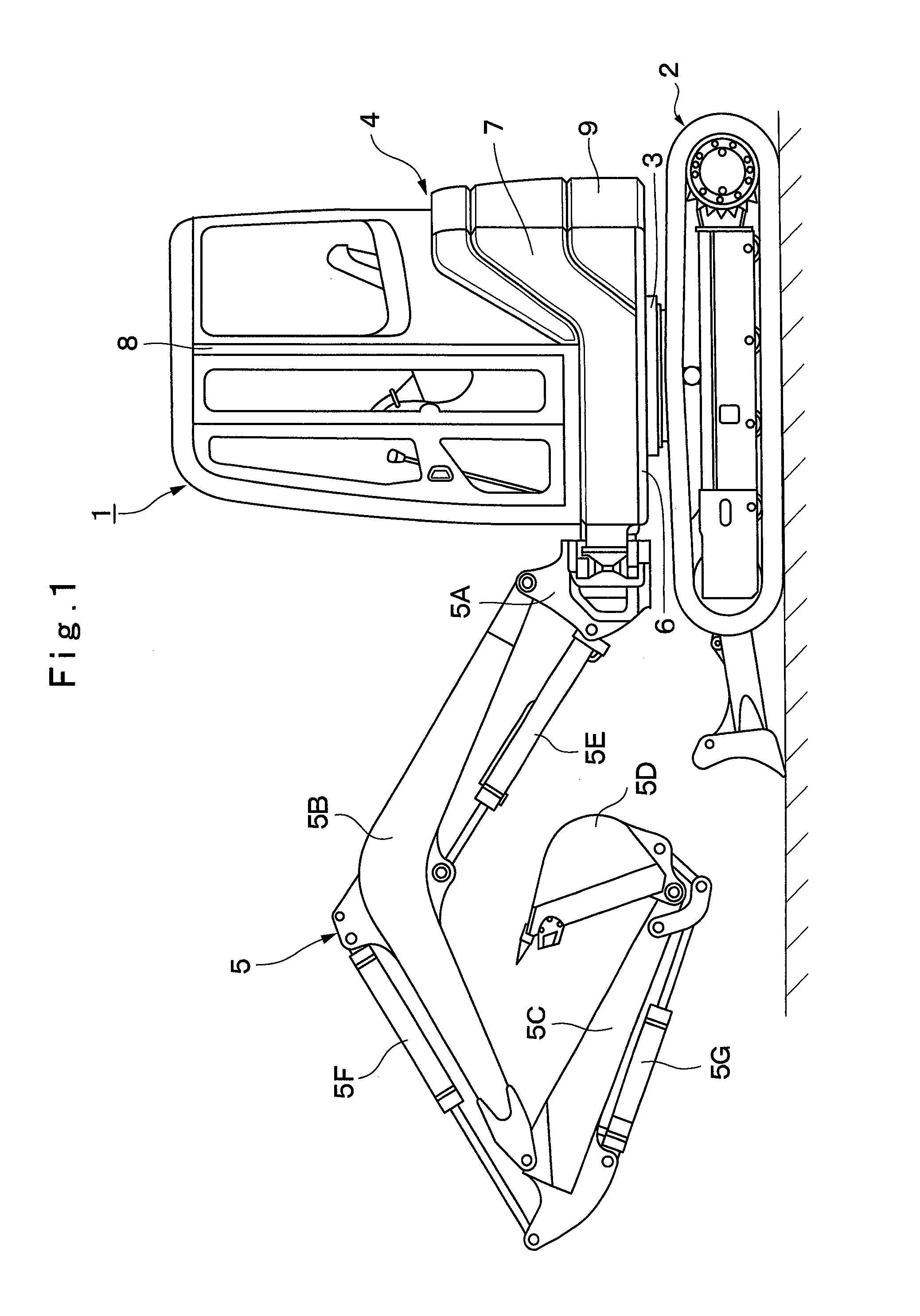
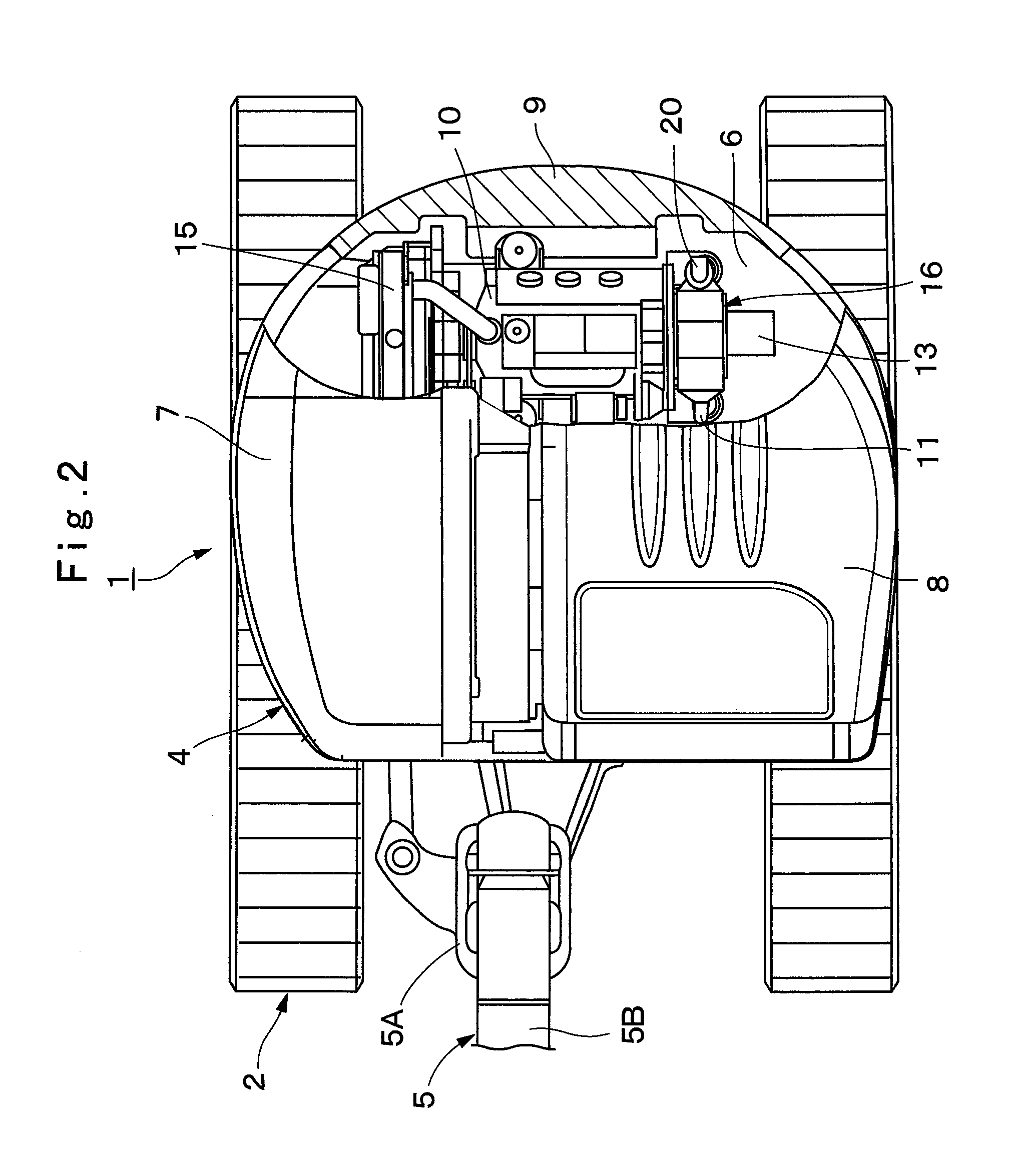
[0040]FIGS. 1 to 7 show a hydraulic excavator according to the present invention.

[0041]In the figures, designated at 1 is a small-sized hydraulic excavator used for an excavating work of earth and sand and the like, an earth removing work and the like. This hydraulic excavator 1 includes an automotive crawler-type lower traveling structure 2, an upper revolving structure 4 rotatably mounted on the lower traveling structure 2 through a revolving device 3 and constituting a vehicle body together with the lower traveling structure 2, and a working mechanism 5 provided capable of moving upward / downward on a front side of the upper revolving structure 4.

[0042]Here, the working mechanism 5 is constituted as a swing-post type working mechanism. This working mechanism 5 includes a swing post 5A, a boom 5B, an arm 5C, a bucket 5D as a working tool, a swing cylinder (not shown), a boom cylinder 5E, an arm cylinder 5F, and a bucket cylinder 5G. The upper revolving structure 4 is constructed wi...

second embodiment

[0103]In the second embodiment, assume that explanation will be made using an example in which, in the previous work using the hydraulic excavator 1, while the operator in the cab 8 rotates the dial 32A of the rotational speed setting device 32 to the position of the set value “Hi” indicated in FIG. 4, the engine 10 is stopped. As a result, if the engine 10 is to be newly started by the starter 28, it is presumed that the target rotational speed Nset of the engine 10 is set to the high idling rotational speed NHi shown in FIG. 5.

[0104]Here, the processing operation shown in FIG. 8 is started. Processing at Step 11 to Step 17 is performed similarly to Step 1 to Step 7 shown in FIG. 7 according to the above described first embodiment. Moreover, if it is determined to be “NO” at Step 13, the routine moves to Step 18, and the engine 10 is started similarly to Step 8 shown in FIG. 7. However, in the second embodiment, in processing at Step 19 subsequent to Step 18, the temporary target r...

third embodiment

[0127]It should be noted that, in the above described third embodiment, the case in which, when the engine 10 is newly started, the dial 32A of the rotational speed setting device 32 is rotated to the position of the set value “Hi”, the target rotational speed Nset of the engine 10 is set to the high idling rotational speed NHi is described as an example. However, the automatic recovery control by the present invention is not limited to that, and the automatic recovery control may be performed along characteristic lines 43 and 44 other than the characteristic line 42 shown in FIG. 10, for example.

[0128]That is, when the engine 10 is newly started, the dial 32A of the rotational speed setting device 32 might have been rotated to a position of a set value “Mh” of medium- to high-speed rotation exemplified in FIG. 4. As a result, the target rotational speed Nset of the engine 10 is set to a rotational speed NMh at a medium- to high-speed lower than the high idling rotational speed NHi ...


PUM


Abstract

A control device for driving / controlling an engine on the basis of a signal from a temperature state detector, a rotation detector, and a rotational speed setting device is provided. The control device includes a start temperature determining processing unit configured to determine whether or not a temperature (T) at start of the engine is less than a predetermined temperature (Tw1) and a start control processing is performed in accordance with a set value of a target rotational speed (Nset) by the rotational speed setting device in case the start temperature (T) is equal to or less than the predetermined temperature (Tw1). This suppresses occurrence of cavitation by stopping the start of the engine (10) within a range in which the temperature (T) is equal to or lower than the predetermined temperature (Tw1) and the target rotational speed (Nset) of the engine (10) is higher than a predetermined threshold value (Nca).

Description

TECHNICAL FIELD[0001]The present invention relates to a construction machine such as a hydraulic excavator and the like on which an electronically controlled engine is mounted.BACKGROUND ART[0002]As a construction machine represented by a hydraulic excavator, those on which an electronically controlled diesel engine is mounted as a prime mover are known. In such diesel engine, an exhaust gas purifying device for removing harmful substances in an exhaust gas is provided. On the other hand, by using an electronically controlled fuel injection device, a fuel injection quantity or an injection timing can be controlled with high accuracy. Thus, as compared with a mechanical fuel injection device, startability at a low temperature in a cold area can be improved, and time required for warming-up operation can be reduced (Patent Document 1).PRIOR ART DOCUMENTPatent Document[0003]Patent Document 1: Japanese Patent Laid-Open No. 2008-82303ASUMMARY OF THE INVENTION[0004]The above described con...

Claims


Application Information

Patent Timeline
Patent Type & Authority Patents(United States)
IPC IPC(8): E02F9/22F02D29/02F02D1/16F02D31/00E02F3/32
CPCE02F9/2246E02F3/325E02F9/2285E02F9/2296F02D1/16F02D29/02F02D31/008F02D2001/167F02D41/064F02D2200/021F02D41/065F02D2250/02F02N11/106F02D31/007
Inventor YOSHIDA, HAJIMENOGUCHI, SHUUHEIMOTOZU, MAKOTO
Owner NIHON KENKI CO LTD
Learn More