
Method and apparatus for controlling a hybrid power system

a hybrid power system and power technology, applied in the direction of transportation and packaging, dc source parallel operation, energy industry, etc., can solve the problem of energy being drawn from the utility grid

Active Publication Date: 2015-07-28
FAITH TECH INC
View PDF21 Cites 32 Cited by
  • Summary
  • Abstract
  • Description
  • Claims
  • Application Information

AI Technical Summary

Benefits of technology

This approach simplifies power control, reduces double power conversion, and enhances flexibility by enabling efficient energy management and storage, accommodating variable renewable energy sources while maintaining grid stability.

Problems solved by technology

Similarly, energy may be drawn from the utility grid when the power generated by the sources fails to meet the power demanded by the power system

Method used


Image

  • Method and apparatus for controlling a hybrid power system
  • Method and apparatus for controlling a hybrid power system
  • Method and apparatus for controlling a hybrid power system

Examples


Embodiment Construction

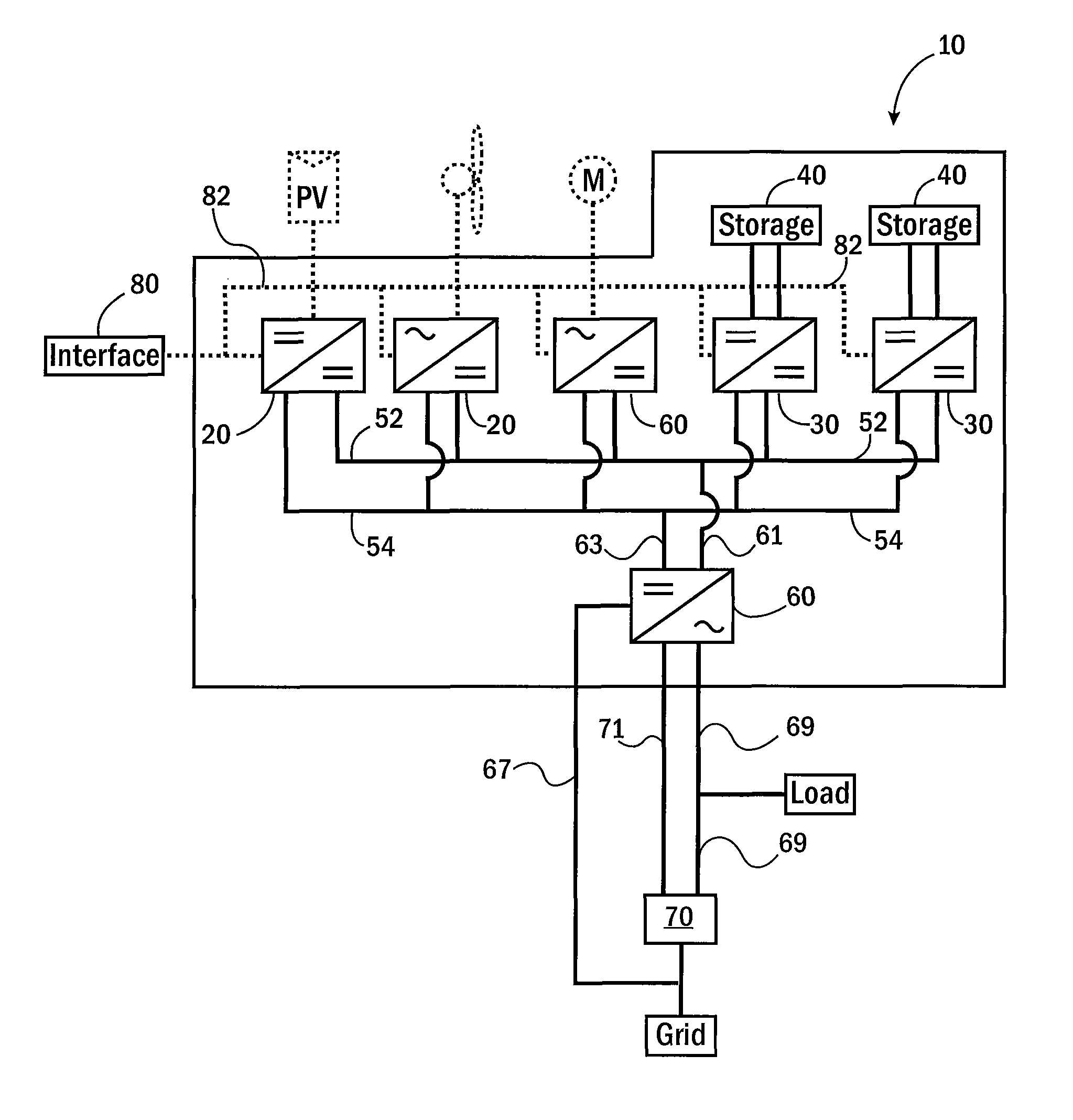
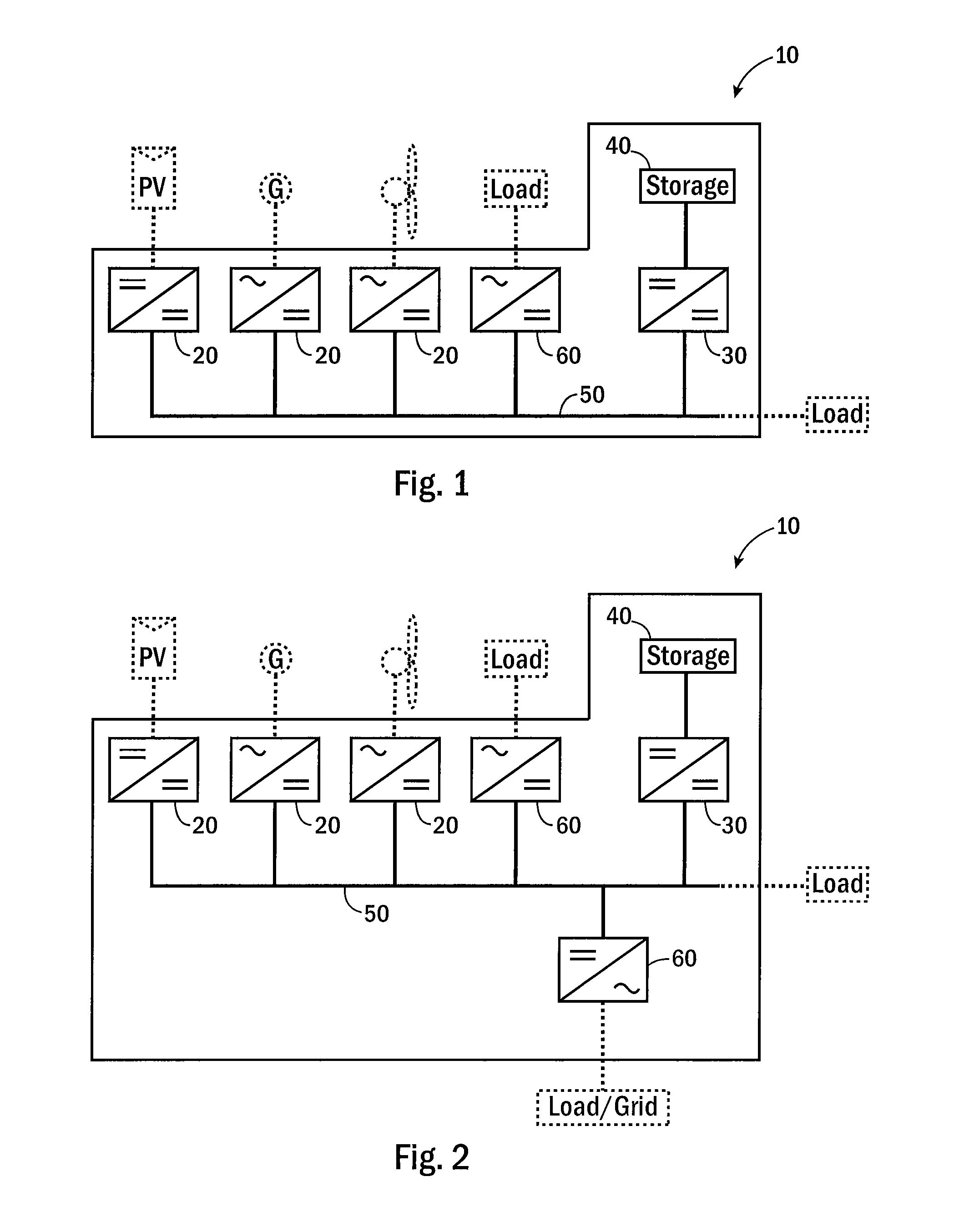
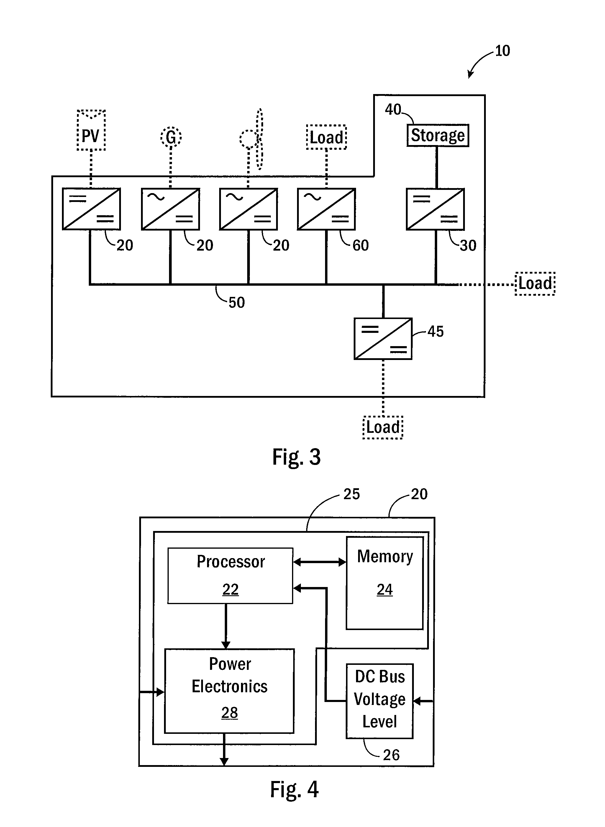
[0044]The present invention provides a method and apparatus of controlling a hybrid power system 10. Specifically, this invention manages power flow or energy transfer among one or more power generating sources, storage devices, loads, and the utility grid, each of which is coupled to a common DC bus 50, either directly or by a power conversion device.

[0045]Throughout this description, several terms will be used for describing the power conversion devices used to couple a generating source or load to the common DC bus 50, including: a converter 20, a regulator 30, and an inverter 60. Referring to FIGS. 4-6, each of the converter 20, regulator 30, and inverter 60 include both a voltage signal 26, 36, 66 and a control unit 25, 35, 65. The voltage signal 26, 36, 66 indicates the voltage level present on the DC bus 50 and may be generated by individual voltage sensors within each power conversion device, a single voltage sensor providing the signal to multiple power conversion devices, ...


PUM


Abstract

The present invention provides a simplified method of controlling power among the various sources and loads in a power system. Power generating sources are each connected to a common DC bus through a converter. The converter selectively transfers energy to the DC bus at a maximum rate or at a reduced rate according to the level of the DC voltage present on the DC bus. At least one storage device is preferably connected to the common DC bus through a power regulator. The power regulator selectively transfers energy to or from the DC bus as a function of DC voltage level present on the DC bus. Further, an inverter may be provided to bidirectionally convert between the DC voltage and an AC voltage for connection to a customer load or the utility grid. Each power conversion device is independently controlled to provide a modular and simplified power control system.

Description

CROSS-REFERENCE TO RELATED APPLICATIONS[0001]This application is a continuation-in-part of U.S. patent application Ser. No. 12 / 355,169, filed Jan. 16, 2009, now U.S. Pat. No. 8,008,808 the entire contents of which is incorporated herein by reference.BACKGROUND OF THE INVENTION[0002]1. Field of the Invention[0003]The invention relates to a method and apparatus of controlling a hybrid power system. Specifically, this invention manages energy transfer and power flow among one or more power generating sources, storage devices, loads, the utility grid, an off grid power system, or a combination thereof, each of which is coupled to a common DC bus.[0004]2. Discussion of the Related Art[0005]In recent years, increased demands for energy and increased concerns about supplies of fossil fuels and their corresponding pollution have led to an increased interest in renewable energy sources. Two of the most common and best developed renewable energy sources are photovoltaic energy and wind energy...

Claims


Application Information

Patent Timeline
Patent Type & Authority Patents(United States)
IPC IPC(8): H02J1/00H02J1/10H02J7/34H02J3/38
CPCH02J1/10H02J7/34H02J3/382H02J2001/104Y02E10/563Y02E10/566Y02E10/763Y02E10/766H02J2300/40H02J2300/28H02J2300/20H02J2300/24H02J3/381Y02P80/20H02J3/46H02J3/42H02J3/388Y02E10/56Y02E10/76
Inventor DENNIS, KEVINRAASCH, MICHAELVANG, DER
Owner FAITH TECH INC
Learn More