Power harvesting bearing configuration

a technology of power harvesting bearings and configurations, applied in the direction of bearing unit rigid support, bearing cooling, liquid fuel engines, etc., can solve the problems of limited supply and thus limited run time, affecting the efficiency of rotating elements of the system, and requiring extensive and costly power cabling and support equipment, so as to reduce the availability or ease of providing electrical power, the effect of generating a continued electrical curren

Inactive Publication Date: 2015-08-04
AB SKF
View PDF13 Cites 1 Cited by
  • Summary
  • Abstract
  • Description
  • Claims
  • Application Information

AI Technical Summary

Benefits of technology

[0035]One advantage of the present invention is the ability to generate a continued electrical current using a cooling system of a bearing assembly. One or more sensors can be employed to monitor a condition of a bearing. The sensors are commonly operated using electrical power. The sensors can monitor a variety of parameters to continuously determine a condition of a bearing. Communication devices could be employed as a vehicle to transfer information to a remote monitoring facility. These communication devices are also operated using electrical power. It is not uncommon where a system utilizing a bearing would be located in a remote area where sourcing electrical power could be difficult. Bearings can be utilized on equipment deployed in remote locations. The application of the bearing may limit the availability or ease of providing electrical power to the sensors used to monitor the condition of the bearing. The inclusion of an electrical power-generating device within a bearing system eliminates the need for an external source of electrical power. Additionally, by integrating the turbine assembly into the cooling system, the electrical energy is not drawing energy from the rotation of the bearing or other rotating elements of the system. Therefore, the turbine assembly is not impacting the efficiency of the rotating elements of the system.
[0036]Another advantage of the present invention is the ease of installation. The installation can be accomplished by inserting the turbine assembly into a cooling system port. The cooling system port can be an inlet port or a discharge port. When necessary, the cooling system port can be enlarged and / or deepened to accommodate the turbine assembly.
[0037]The location of condition monitoring sensors could complicate any provisions for externally provided power for monitoring the condition of the bearing. The bearing(s) can be integrated into the equipment at a location that is difficult to access, particularly for wiring. The inclusion of a power generator within the bearing assembly optimizes a source for electrical power at a location proximate the sensors or other equipment requiring the electrical power. This significantly reduces a length of wiring required. The reduced wiring avoids any accidentally interference or abrasion by any rotational movements or other movements of components of the equipment.
[0038]Another advantage of the present invention is the ability to deploy a temporary system having an integrated turbine for portable, monitored systems. The solution enables a complete stand-alone wireless system.

Problems solved by technology

Batteries provide a limited capacity, which dictates a limited supply and thus a limited run time.
Obtaining power from a commercial utility source can be costly, particularly for remote installations.
Transferring electrical power from a commercially available source can require running extensive and costly power cabling and support equipment.
Replacement of batteries incurs both parts and labor costs.
A portion of the bearings generates a significant amount of heat.
The application of the bearing may limit the availability or ease of providing electrical power to the sensors used to monitor the condition of the bearing.

Method used


Image

  • Power harvesting bearing configuration
  • Power harvesting bearing configuration
  • Power harvesting bearing configuration

Examples


Embodiment Construction

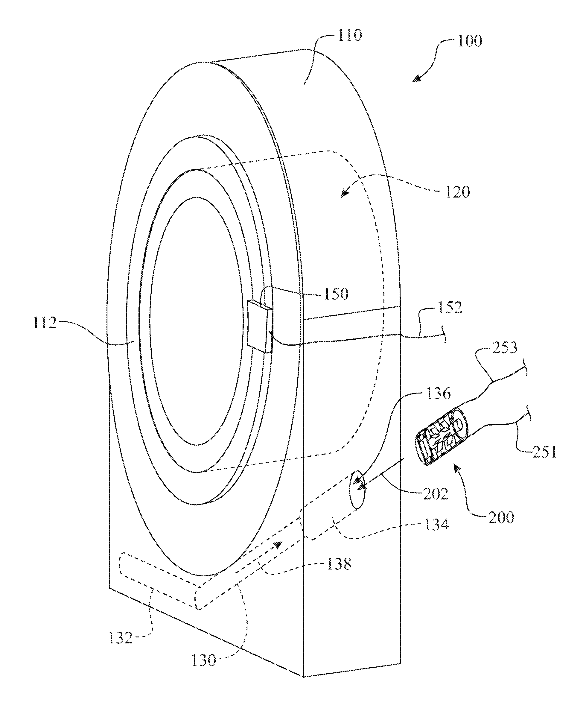
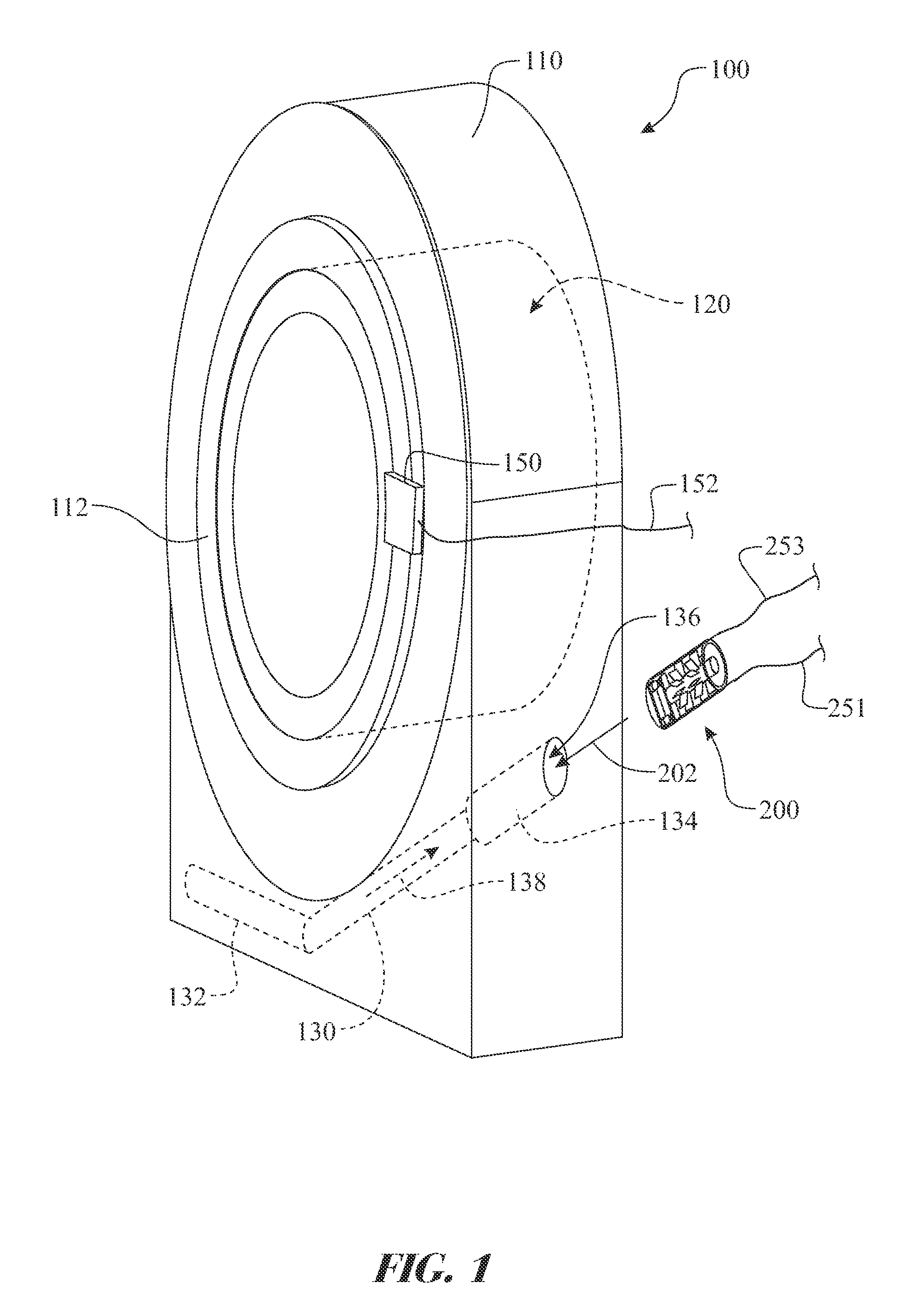
[0046]The following detailed description is merely exemplary in nature and is not intended to limit the described embodiments or the application and uses of the described embodiments. As used herein, the word “exemplary” or “illustrative” means “serving as an example, instance, or illustration.” Any implementation described herein as “exemplary” or “illustrative” is not necessarily to be construed as preferred or advantageous over other implementations. All of the implementations described below are exemplary implementations provided to enable persons skilled in the art to make or use the embodiments of the disclosure and are not intended to limit the scope of the disclosure, which is defined by the claims. For purposes of description herein, the terms “upper”, “lower”, “left”, “rear”, “right”, “front”, “vertical”, “horizontal”, and derivatives thereof shall relate to the invention as oriented in FIG. 1. Furthermore, there is no intention to be bound by any expressed or implied theo...


PUM


Abstract

A power generating bearing assembly comprising a bearing retained by a bearing housing is provided. The bearing housing includes a bearing cooling passage system comprising at least one integrated liquid cooling passage is integrated within the bearing housing. A turbine assembly is inserted within the integrated liquid cooling passage, wherein fluid flowing within the integrated liquid cooling passage causes a turbine blade subassembly within the turbine assembly to rotate. The rotation of the turbine blade subassembly rotates an electrical power generator to create electrical power. The turbine assembly can be integrated into any existing bearing assembly comprising a bearing cooling passage system. It is preferred to seat the turbine assembly within a cooling system port of the bearing cooling passage system.

Description

CROSS-REFERENCE TO RELATED APPLICATIONS[0001]This application is the U.S. National Stage of International Application No. PCT / EP2012 / 069073 filed on Sep. 27, 2012, which claims priority to U.S. patent application Ser. No. 61 / 544,107 US filed on Oct. 6, 2011.[0002]Technical Field Of The Invention[0003]The present invention relates to an apparatus and method for generating power utilizing a cooling system integrated into a bearing or bearing housing.[0004]2. Background Art[0005]Bearings are used to support many rotating objects. Bearings are commonly integrated into a variety of machines. The bearings are a key factor contributing to the reliability of the machine. The system designed commonly installs one or more bearing condition monitoring devices to ensure the bearings remain in working order. The majority of the condition monitoring devices requires low voltage electrical power for operation. Some systems include other components that also utilize electrical power.[0006]Batteries...

Claims


Application Information

Patent Timeline
Patent Type & Authority Patents(United States)
IPC IPC(8): F16C41/00H02K7/18F01D15/10F16C35/00F16C37/00F01D1/04F04D29/05
CPCF16C35/00F16C37/00F16C41/004F01D1/04F01D15/10H02K7/1823F04D29/05
Inventor VAN DER HAM, ANDREAS CLEMENSBARTL, FRANK
Owner AB SKF
Why Eureka
Try Eureka