Chlorination device

a chlorination device and chlorination technology, applied in the direction of dissolving, other chemical processes, separation processes, etc., can solve the problems of chlorination source degradation, insufficient amount of disinfectant, and unsafe drinking water supply of contaminated water

Active Publication Date: 2015-08-11
MEDENTECH
View PDF14 Cites 1 Cited by
  • Summary
  • Abstract
  • Description
  • Claims
  • Application Information

AI Technical Summary

Benefits of technology

[0028]The invention provides a device which adjusts the amount of disinfectant added proportional to the flow to ensure a similar level of disinfectant. The device does not require electricity to control metering. The device drains down when there is no flow and therefore ensures that solid disinfectant does not continue to dissolve. The device is vented to prevent a build up of dangerous fumes. The device is readily adjusted to change the amount of disinfectant added. The device is small so that it can be easily mounted on a ballcock fill valve, often used on gravity tanks, or on a water dispensing tap. The device discharges at zero pressure head to ensure constant operation. The device is easily inspected without shutting down to see if it needs recharging. The device can discharge water downwards to make it easier to fill a tank or water container.

Problems solved by technology

In many parts of the world a plumbed water supply may not be safe to drink because of microbial contamination.
Sometimes water in municipal schemes is not disinfected or the amount of disinfectant added may not be sufficient to provide residual protection to the water to prevent microbial recontamination.
One of the problems with such systems is that when flow is turned off water is retained in the device leading to problems of degradation of the chlorine source.
Such a concentrated slug is undesirable.

Method used


Image

  • Chlorination device
  • Chlorination device
  • Chlorination device

Examples


example 1

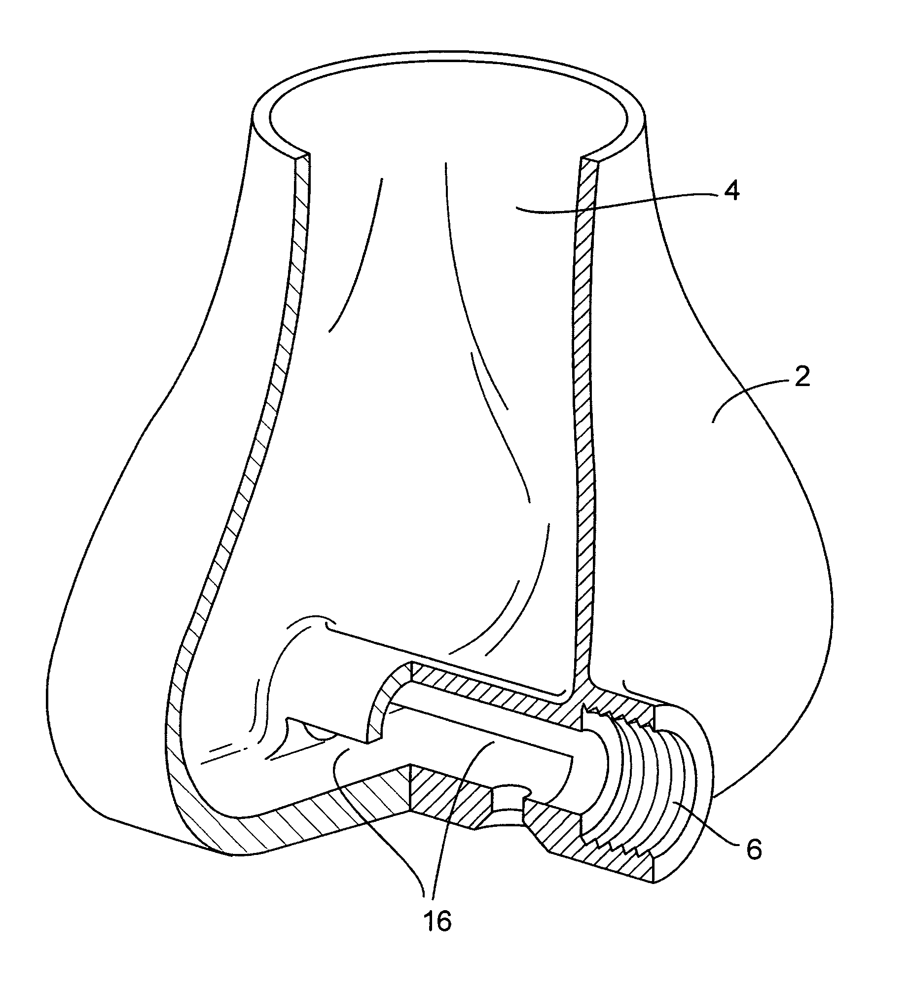
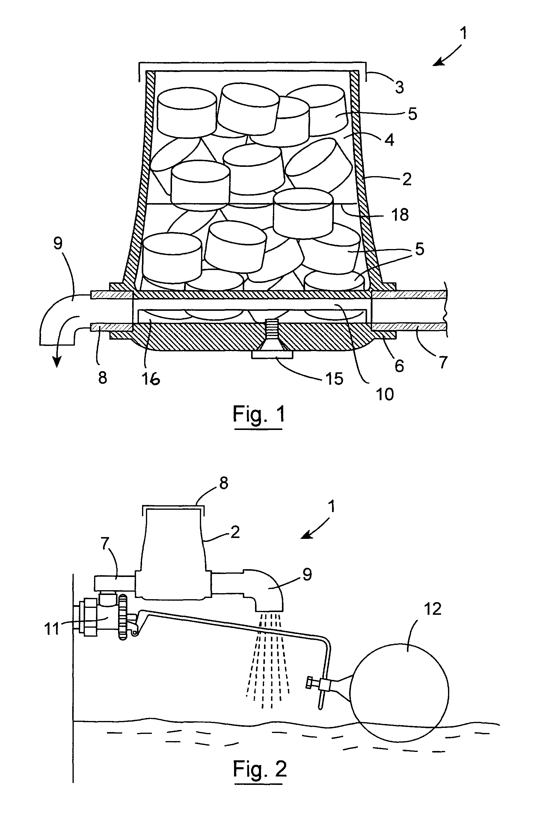
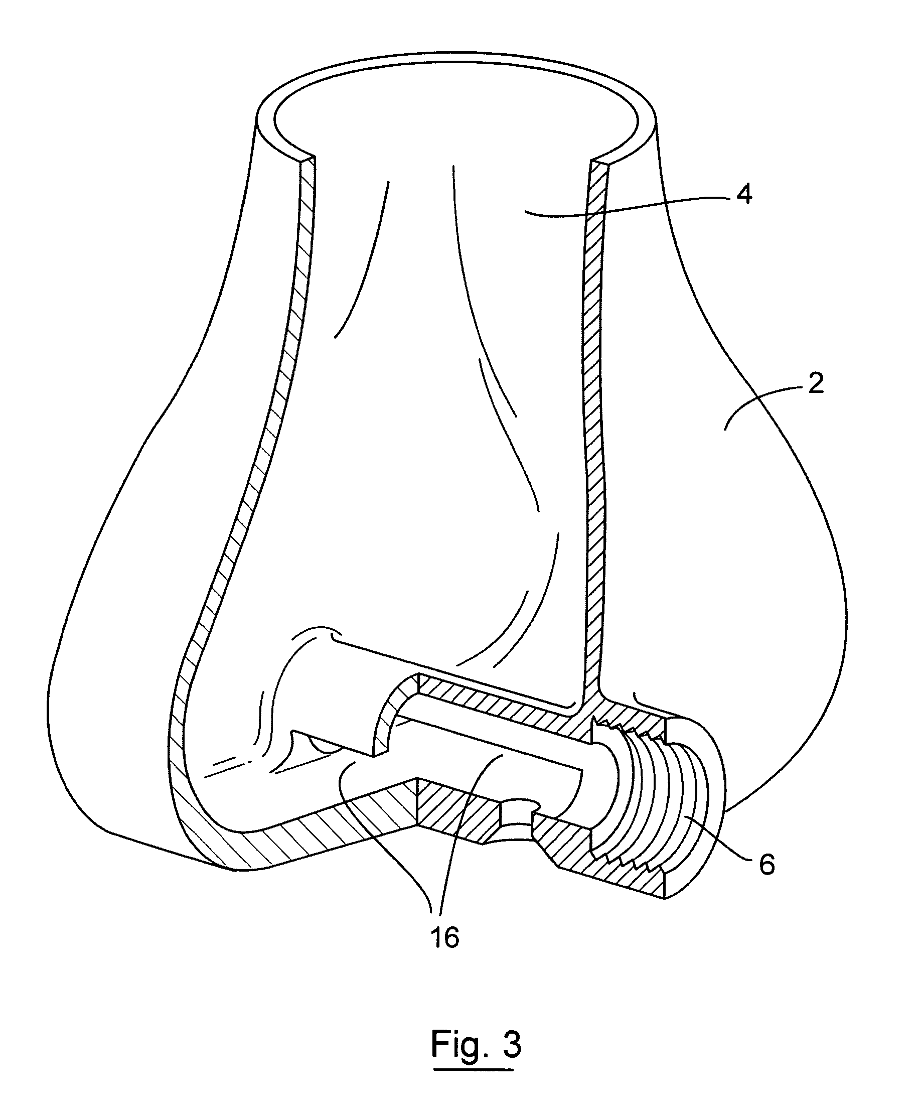
[0062]The device shown in FIG. 3 was moulded from a nylon type material using selective laser sintering. The overall size is approximately 100 mm across by 50 mm long by 100 mm high. The passage 10 through the device is 12 mm in diameter and ends are machined out and threaded with ½″ BSP Thread. There is a slot 11 5 mm high at the bottom of this pipe 10 which allows water to flow into the chamber 4. ½″ ID piping 7 can be connected to the inlet 6. The outlet 8 is also threaded with ½″ BSP and is fitted with a ½″ to ¾″ expanding nipple with ¾″ bend 9 attached and pointing downwards. The hole in the bottom of the device is threaded with M8 threads and is fitted with a stainless steel M8 screw 15 of suitable length such as 16 mm.

[0063]The device is first operated without tablets 5 and the depth of water is measured in the device. Screw lengths of 12 mm or 16 mm are used to set a depth of around 30 mm for maximum flow of 1000 L / hour. Once set tablets 5 are added to the chamber 4. Even wh...

example 2

[0064]The device of Example 1 is attached to the outlet of ballcock valve shown in FIG. 2. The ballcock valve (Beta BS1212 from Beta Ballvalves Ltd, Wolverhampton, England) discharges upwards. A right angled custom part is threaded at the inlet with M12×1 thread of the ball valve to ½″ BSP. The ballvalve with attached device is mounted in a tank much like that used as a gravity reservoir in household and farm water systems. The device is set up much as in Example 1. However, maximum flow rates through the orifice of the ballvalve are slower than in example 1. Nevertheless, when set up and filled with tablets as outlined in example 1 the amount of chlorine added to the water remains in the range 3-5 ppm no matter how much water is flowing though the ball valve.

[0065]Referring to FIGS. 4 to 15, there is illustrated another unpressurised chlorination device 20 according to the invention. Parts similar to those identified with reference to FIGS. 1 to 3 are assigned the same reference nu...


PUM

PropertyMeasurementUnit
angleaaaaaaaaaa
sizeaaaaaaaaaa
sizeaaaaaaaaaa

Abstract

An un-pressurized chlorination device comprises a container having an open top closed by a removable lid. The container defines an inner chamber for a plurality of chlorination tablets. The container has a lower inlet spigot for receiving a water supply inlet pipe. The container also has a lower water outlet through which chlorinated water is delivered. There is a water flow path between the inlet and the outlet. The tablet chamber is not pressurized and the outlet discharges to atmosphere pressure. The device of the invention is useful for dissolving, dispersing and dispensing soluble material in tablet form into a liquid. There is a substantially horizontal fluid path with just enough fall to the outlet to allow the device to drain down out of the outlet when there is no inlet flow.

Description

[0001]This is a national stage of PCT / IE10 / 000051 filed Aug. 18, 2010 and published in English, claiming the benefit of U.S. provisional application No. 61 / 272,123, filed Aug. 18, 2009, and the U.S. provisional application No. 61 / 344,102, filed May 25, 2010, hereby incorporated by reference.[0002]The present invention relates to a device used to chlorinate water to make it potable. The device may also be used to chlorinate waste water, cooling tower water and swimming pool water. The device may also be used to dissolve other materials, which may be in a tablet form, into a liquid.[0003]In many parts of the world a plumbed water supply may not be safe to drink because of microbial contamination. Sometimes water in municipal schemes is not disinfected or the amount of disinfectant added may not be sufficient to provide residual protection to the water to prevent microbial recontamination. In other cases water may be piped directly from a river or other surface source or a well as part...

Claims


Application Information

Patent Timeline
Patent Type & Authority Patents(United States)
IPC IPC(8): C02F1/68C02F1/76B01F1/00C02F1/00
CPCC02F1/006C02F1/688B01F1/0022C02F1/76C02F2209/40B01F21/22B01F21/20
Inventor STAFFORD, ULICK
Owner MEDENTECH
Why Eureka
Try Eureka