Solvent delivery system for liquid chromatography that maintains fluid integrity and pre-forms gradients

a liquid chromatography and fluid integrity technology, applied in the field of analytical techniques, can solve the problems of increasing the difficulty of maintaining the proper mixture of the gradient, reducing the accuracy of the gradient, so as to prevent cross-flow and back-flow contamination, reduce the loss of maximum operating pressure, and avoid feedback instability

Active Publication Date: 2015-08-11
WATERS TECH CORP
View PDF17 Cites 6 Cited by
  • Summary
  • Abstract
  • Description
  • Claims
  • Application Information

AI Technical Summary

Benefits of technology

[0018]The invention addresses the problems above and others by providing systems and methods for delivering solvents to liquid chromatography devices. The inventors have discovered that by using a feed forward control strategy to compensate the effects of fluid compressibility, with conventional closed-loop feedback control, the ultimate preparation and delivery of the solvent can be greatly improved.
[0040]It is another advantage of the subject technology to accomplish changing the flow rate in a simple, efficient and quick manner without adding to the complexity of the system. Yet another advantage is the ability to overcome the long time constant in trapping applications.

Problems solved by technology

The delivery of the gradient is often under demanding constraints such as high pressure, e.g., high pressure liquid chromatography (HPLC) systems.
Despite the advances noted above, many inherent limitations remain in nano-flow LC systems.
As a run may take an hour, this increases the difficulty of maintaining the proper mixture of the gradient under challenging circumstances.
However well-suited to the particular application, nano-scale transducers have a limited dynamic range and are detrimentally subject to thermal effects.
Formation of the gradient over a typical period, such as an hour, during which the temperature can fluctuate results in a poor mixture consistency because of the thermal drift of the transducer.
Further, on a nano-scale where the transducers may only hold 2 μL of fluid, the high pressure compression of the fluids generates erroneous transducer readings which spoil the mixture.
High pressure operation is also at the edge of the tranducer's dynamic range where noise levels can become unacceptable.
In short, limited range, noise and thermal drift associated with the transducers are obstacles to meeting the desired performance.
This is not an easy performance specification to achieve because the noise level of the device can be as high as + / −5 nL / min, and the thermal sensitivity to noise without thermal compensation can be in excess of + / −4 nL / min per degree Celsius.
Thus, a one degree change of the instrument temperature can result in almost a 50% composition error.
Such attempts at compensating for the affects of the thermal sensitivity greatly increase the complexity of the LC system without addressing the underlying problem.
During bulk or solvent flow change, it is difficult to maintain the desired composition mixture across the mixing point or node.
Due to inherent limitations, such as flow transducers with relatively slow response times (i.e., time constants of several seconds), the necessary feedback is not provided quickly enough to allow the system to be responsive and maintain the desired composition mixture.
Rapid pressure changes from say 10,000 PSI to 200 PSI can cause critical and expensive components like the column to be destroyed.
Also, the compressibility changes of fluid create false readings because the transducers are inherently sensitive to such rapid fluid density changes as the back pressure swings across the typically large range of pressure, and to some extent, the adiabatic heating effect of the fluids.
Thus, LC systems that regulate flow between multiple solvent pumps using feed back control cannot maintain accurate measured flow due to the effects of the rapid compressibility changes and heating on the nano-flow transducers.
Another disadvantage of prior art LC systems is cross-flow and back-flow contamination of the flow transducers across the mixing node, which results in contamination of the LC system fluid stream and a temporary loss of flow calibration to the transducers.
However, the additional volume becomes lumped with that of the transducers, further exacerbating the rapid compressibility change problems noted above.
Thus, conventional high-pressure mixing systems are very susceptible to cross-contamination across the mixing node at very high pressures.
Further, the cross-contamination across the mixing node can create feedback instability between two flow transducers resulting from the fluidic inter-active coupling.
The cross-contamination also increases the loss of maximum operating pressure, which is attributed to the large parasitic pressure drops associated with much larger decoupling restrictors required by high-pressure mixing systems to passively stabilize the control interaction.
Previous LC systems have recognized these problems and proposed redundant pumps, complex plumbing schemes and valves to isolate the gradient formation pumps from the high-pressure portion of the LC system.
Such costly and complex solutions are not only undesirable but the problems remain.
The valve switching components deter from the reliability of the LC system while increasing the expense and complexity in an unfavorable manner.
Again, the employment of additional components to accomplish peak parking unfavorably increases the expense and complexity of the system.
However, gradient delay and dispersion become problematic.
Further, sample loading time and thereby the whole runtime become undesirably long.
However, there is a need for still better control and prior art systems do not use feed-forward open-loop mechanisms.

Method used


Image

  • Solvent delivery system for liquid chromatography that maintains fluid integrity and pre-forms gradients
  • Solvent delivery system for liquid chromatography that maintains fluid integrity and pre-forms gradients
  • Solvent delivery system for liquid chromatography that maintains fluid integrity and pre-forms gradients

Examples


Embodiment Construction

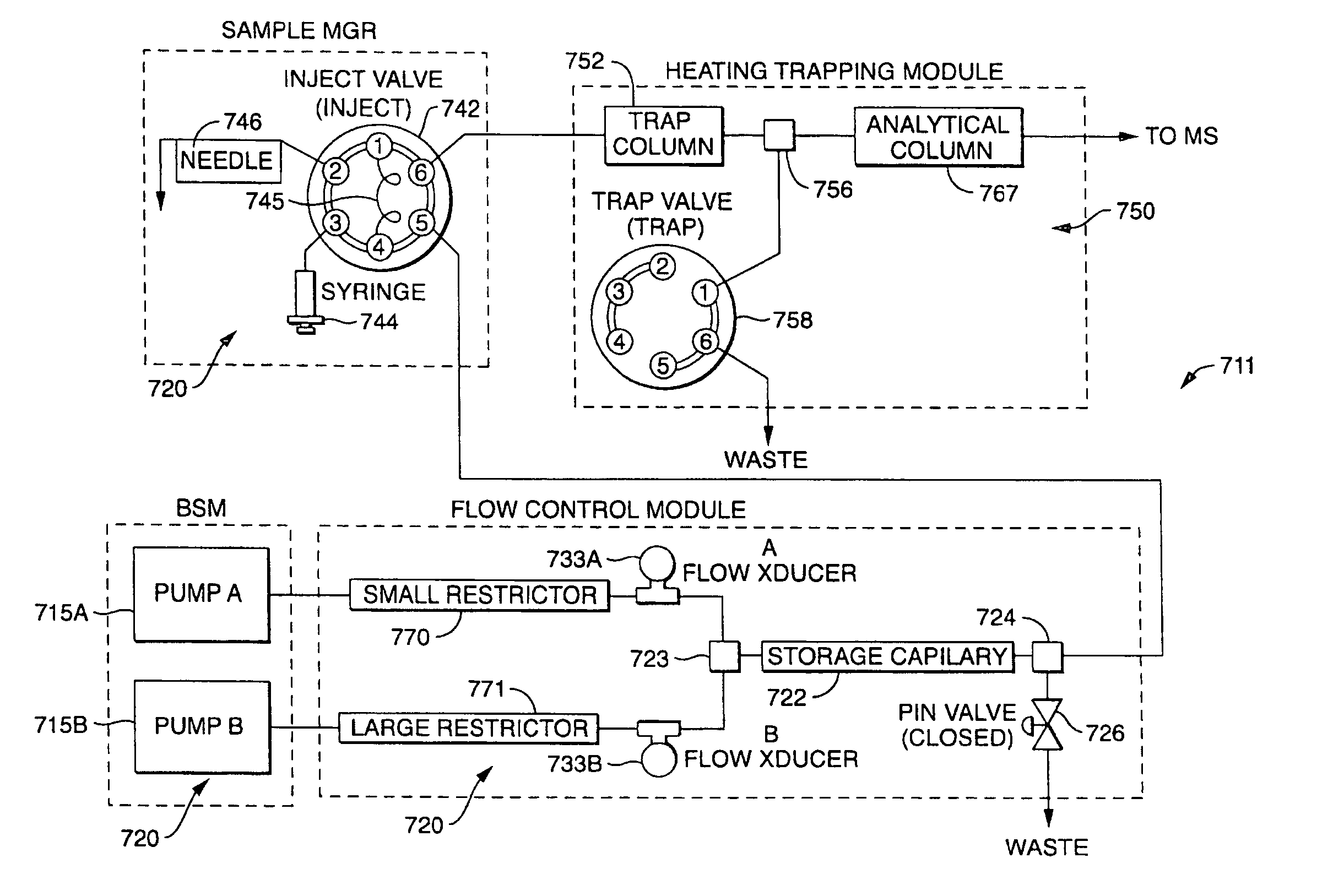
[0079]The present invention overcomes many of the prior art problems associated with delivering solutions to nano-flow capillary LC instruments. The present disclosure maintains the integrity of a fluid mixture by recognizing when undesirable mixing may occur and employing pump settings to prevent such mixing. The present disclosure also illustrates pre-forming gradients a low pressure and high flow in order to increase throughput of LC instruments. The advantages, and other features of the system disclosed herein, will become more readily apparent to those having ordinary skill in the art from the following detailed description of certain illustrative embodiments taken in conjunction with the drawings which set forth representative embodiments of the present invention.

[0080]All relative descriptions herein such as upstream, downstream, left, right, up, and down are with reference to the Figures, and not meant in a limiting sense. Additionally, for clarity, common items such as filt...


PUM

PropertyMeasurementUnit
elution flow rateaaaaaaaaaa

Abstract

A solvent delivery subsystem for a chromatography device performs relatively low pressure, high flow mixing of solvents to form a gradient and subsequent high pressure, low flow delivery of the gradient to the separation column. The mixing of the gradient is independent and does not interfere with the gradient delivery. To form the gradient, the outputs of an aqueous pump and an organic pump are mixed to fill a storage capillary while a downstream point from the storage capillary is vented to atmosphere. After gradient formation, the vent to atmosphere is closed, the solvent delivery system rises to high pressure, and only the aqueous pump runs for gradient delivery. To maintain integrity of the fluid stream, the solvent delivery system uses feed forward compensation and controls at least one parameter selected from the group consisting of pressure and flow in the conduit means to follow a gradual ramp.

Description

CROSS-REFERENCE TO RELATED APPLICATIONS[0001]This application is the U.S. national phase, pursuant to 35 U.S.C. §371, of PCT international application Ser. No. PCT / US2007 / 006679, filed Mar. 16, 2007, designating the United States and published in English on Sep. 27, 2007 as publication WO 2007 / 109157 A2, which claims priority to U.S. Provisional Patent Application Ser. No. 60 / 783,610, filed Mar. 17, 2006. The entire contents of the aforementioned patent applications are incorporated herein by this reference.BACKGROUND OF THE INVENTION[0002]Liquid chromatography (LC) is an analytical technique in which an analyte or sample is examined. A LC system typically has one or more columns that are packed with a stationary phase material. Generally, the term “column” refers to columns, cartridges, capillaries and the like for performing separations of a chromatographic nature. Columns are typically packed or loaded with a stationary phase. This stationary phase can be particulate or beadlike ...

Claims


Application Information

Patent Timeline
Patent Type & Authority Patents(United States)
IPC IPC(8): G01N30/34
CPCG01N30/34G05D11/132G01N30/32G01N2030/326
Inventor CIAVARINI, STEVEN J.PENSAK, JR., STANLEY P.FINCH, JEFFREY W.FADGEN, KEITHLIU, HONGJI
Owner WATERS TECH CORP
Why Eureka
Try Eureka